Recreating the V86P Floppy Drive Riser
One of the things I remember from my original V86P back in the 90s is the way the floppy drives connected to the motherboard. The two drives were mounted back to back, with a riser card between them that connected to a socket on the bottom of the motsherboard. One of the things that would happen after a while is that one of the drives would rattle slightly loose and become disconnected - and thus stop working. The quick fix was to put a disk in both left and right drives and push inward on both disks at the same time - thus reseating the drives back on the riser card. Looking back, and comparing to my current system, I suspect my original system might have been missing one or two of the studs screwed onto the side of the floppy drive, securing it from lateral movement by engaging in holes in the metal battery enclosure.
This system is the hard disk version, so the left drive bay is taken up by a hard disk, which doesn't need to connect to the floppy header at all. When I first opened up the machine, I was surprised to see that the floppy riser appeared to have been snapped, and then taped over. I suspect that this machine was originally built as a dual-floppy model and then converted to the hard disk model. I think the model number on the base is correct for the hard disk model, so this was likely a factory change. The floppy riser looks like it might have been scored and snapped in order to break off the second header, as this would prevent the hard disk fitting into the left drive bay. One downside to this is that the riser doesn't fit in the securing mounts on the floppy brackets to hold it in the correct position, relying solely on the top connector and the friction of the floppy connector to hold it in place.
As part of my hard disk plans, I need to get to the 5V power rail in order to power the CF reader. One option is to pull this from a header on the new drive controller (provided for this purpose) and run the wires around and back under the motherboard. Another option would be to replace the floppy riser board and add a header to provide 5V on the left-drive side, which could be fitted instead of the floppy connector. This would also allow me to add in a floppy drive emulator at some point (either a Gotek or similar), and still keep the physical floppy drive in the right bay.
I didn't remember the original backplane/riser as having any components on it - it was just a PCB with the two floppy headers and a connector for the motherboard, which makes sense because it's essentially just taking the place of a traditional PC floppy cable, complete with the twist between drives A: and B:. The first step in recreating the board was to ring out the existing pinout, which also showed the drives received +5V on pin 1. The drive itself is a Chinon FX-354, and I think the only unusual thing is the lack of a separate power connector.
The next step was to make some detailed measurements of the PCB - it's not a rectangular board, and it's also thinner than usual. Luckily, the first pin of the missing end was still present, so it was possible to get a measurement as to where this header should be in relation to the first. Final width of the board was taken by measuring the space inside the case where the board mounts.
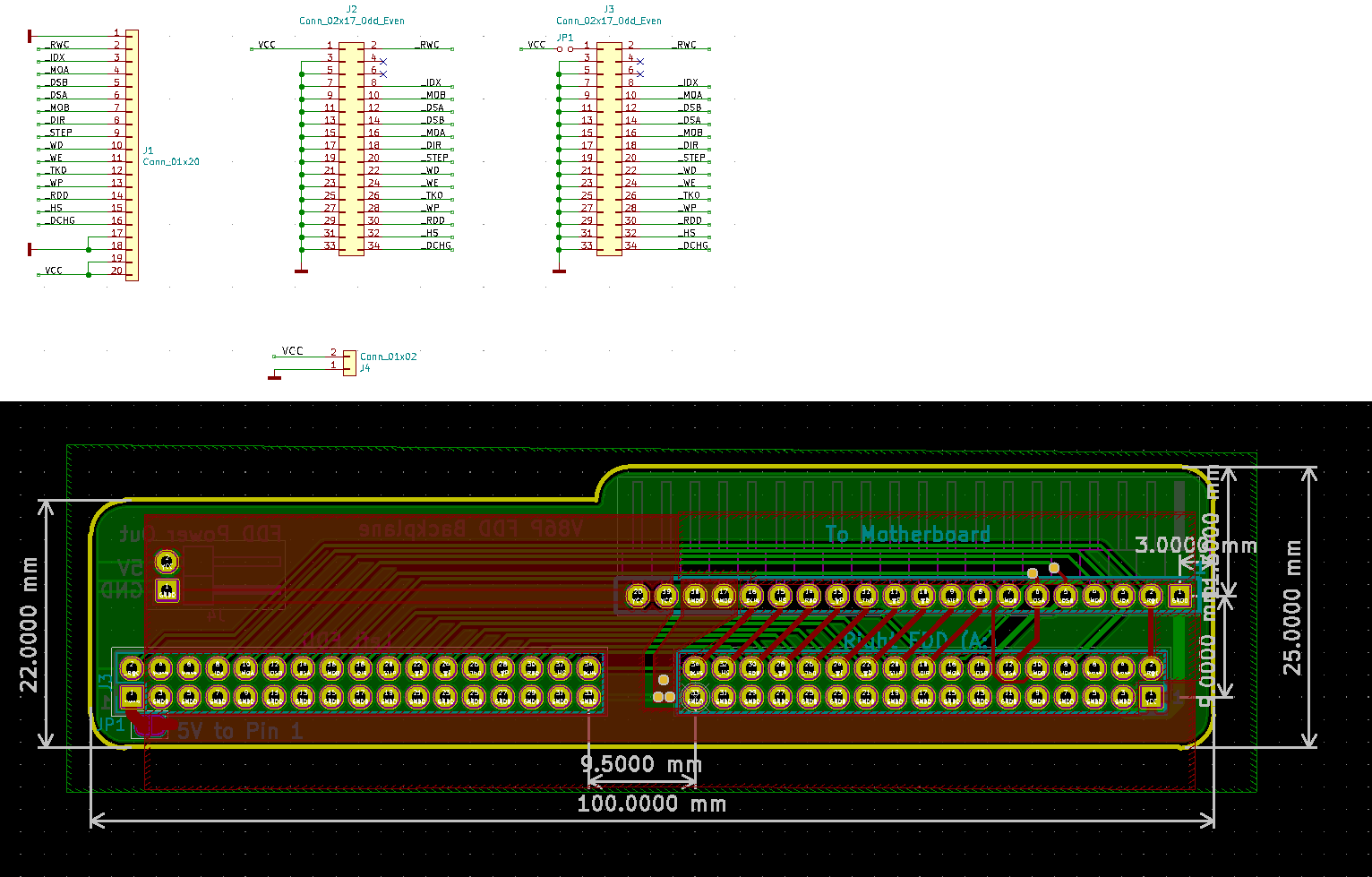
Once I knew the pinout and the dimensions, it was a relatively simple job to turn that into a schematic in kicad, adding in a two pin header for +5V and Gnd, and a solderpad jumper between pin 1 of the second drive connector and +5V - this means that if I want to use a floppy emulator, this header is the same pinout as a regular PC floppy connector, whilst at the same time remaining a drop-in replacement for the original riser (just connect the pads on the solder jumper). Once the schematic was complete, the dimensions taken from the original board were translated into a PCB layout and then gerbers created
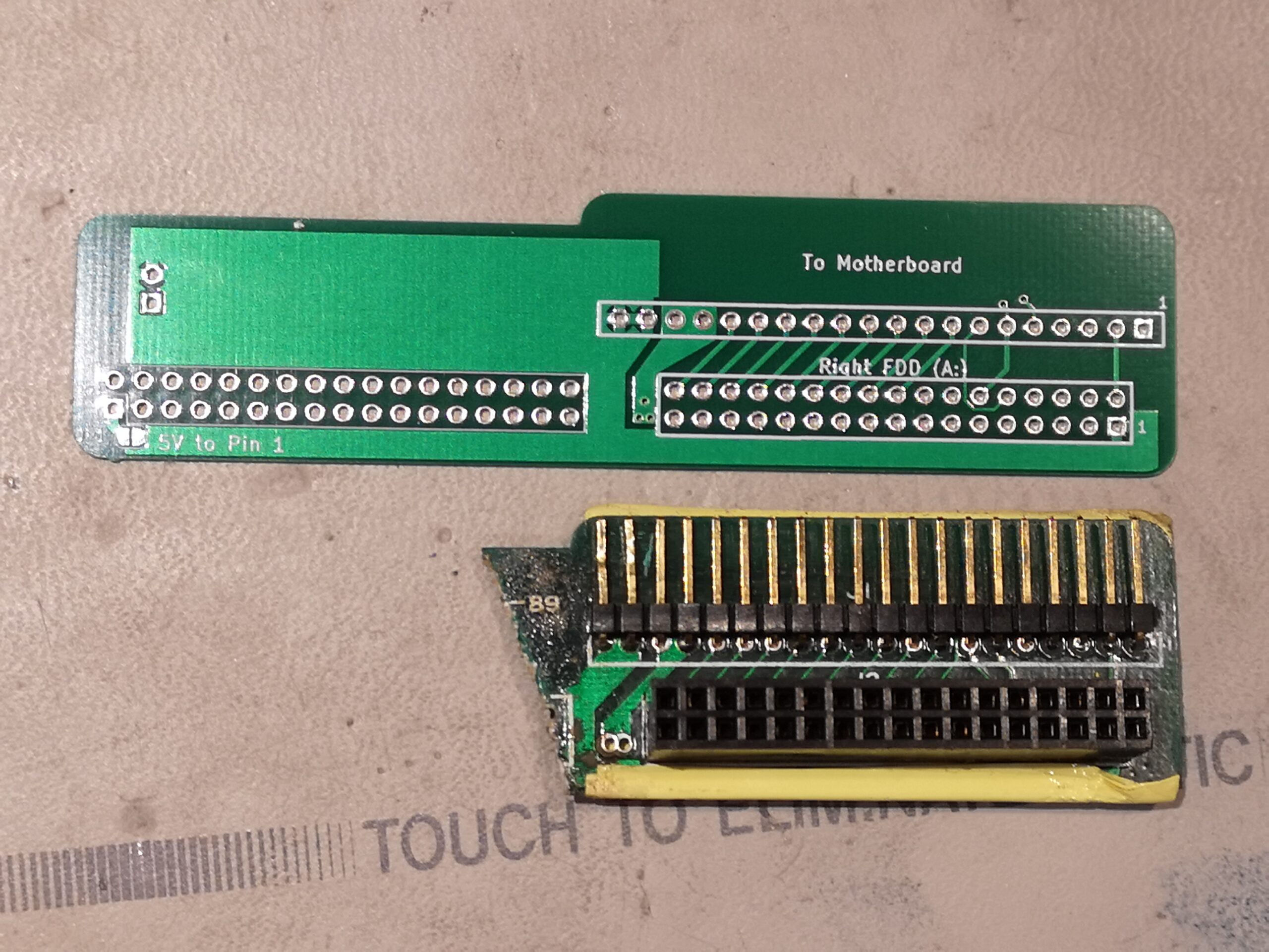
 I sent the gerbers off to Elecrow, making sure to select the correct thickness board (0.8mm), than it was just a matter of waiting. When the new boards arrived, the first thing I did was overlay one over the original board and make sure the physical dimensions lined up - which they did. The next thing was to ring out the pinout and make sure I'd got the layout correct electrically, which was also good. Once I'd confirmed that all looked right, I did a test fit of some pin headers, and discovered that the pin headers on the original board that connect to the motherboard are longer than usual. In fact, when looking more closely, it looks like they used straight pins and then bent them to almost 90° - this is also evident on the back side, where the protruding end of the pins are obviously short and haven't been trimmed short after soldering. In the end, I found some appropriate 90-degree pins that were longer, and had the plastic spacer facing the correct way.
Next was to try a dry-fit in the system - again it fit without any issues, correctly sitting into the supports present on the case and floppy drive mounting rails. With this all good, I set about soldering up a board and then installing it in the laptop in place of the original board. The system booted perfectly, and I had no issues accessing data on the floppy drive.


Next time - a modern replacement for the hard disk controller
Leave a comment
You must be logged in to post a comment.