Floppy Disk Drive ID Switcher
Currently a work in progress - I'll update this with more information as I go.
This little project came about when I started using a Gotek floppy emulator with some of my retrocomputers. Having hundreds of floppy images available at the push of a button is great, not to mention the lack of read/write errors and degrading media; however it's somehow not the same experience as physically swapping disks, and even with some of the sound hacks, it just doesn't sound right. For this reason, I like to keep floppies around in addition to using a Gotek, and it's easy enough to have both connected to a machine at once. Where things get marginally more complicated is when you want to change whether to boot from the FDD or the Gotek. Many systems only boot from the first drive (0 or A), and even in cases where you can tell it to boot from a different drive, a lot of games assume their disk is in the first drive.
It's a simple matter to switch around drive select lines - in fact, it's been pretty common to do this with a simple DPDT switch in line with the drive 0 and drive 1 select lines for a while. You just wire the switch to toggle between pass-through and cross-over, and splice it into the floppy cable between the controller and the two floppy drives. So why complicate matters with ICs?
I have a couple of machines of the all-in-one system unit design, where the system board, keyboard, floppy drive, etc are in a single moulded case and all you have to do is connect up a PSU and monitor (think Amiga A500, A600, A1200, Atari ST, ZX Spectrum +3, etc). There are 3D-printed mounts to install a Gotek internally in most of these systems, but in many cases it's a bit of a squeeze if you don't want to start cutting holes in the case. Likewise if you want to install a drive select swap switch, you need to mount it somewhere, which either means hanging it out the back on a piece of wire, or making holes in the case. Both of which are something I'd like to avoid. In an ideal world, I would like to have a system that cosmetically looks unaltered (i.e. no extra holes or things hanging out), but to which you can connect an external Gotek that has a drive-select switch that lets you toggle between an internal drive 0 and gotek drive 1, and the gotek as drive 0 and the internal drive as drive 1. Not to mention that if the Gotek isn't connected, the system just behaves as normal as internal drive 0. This would have the added benefit that you didn't need to have a Gotek for every single system.
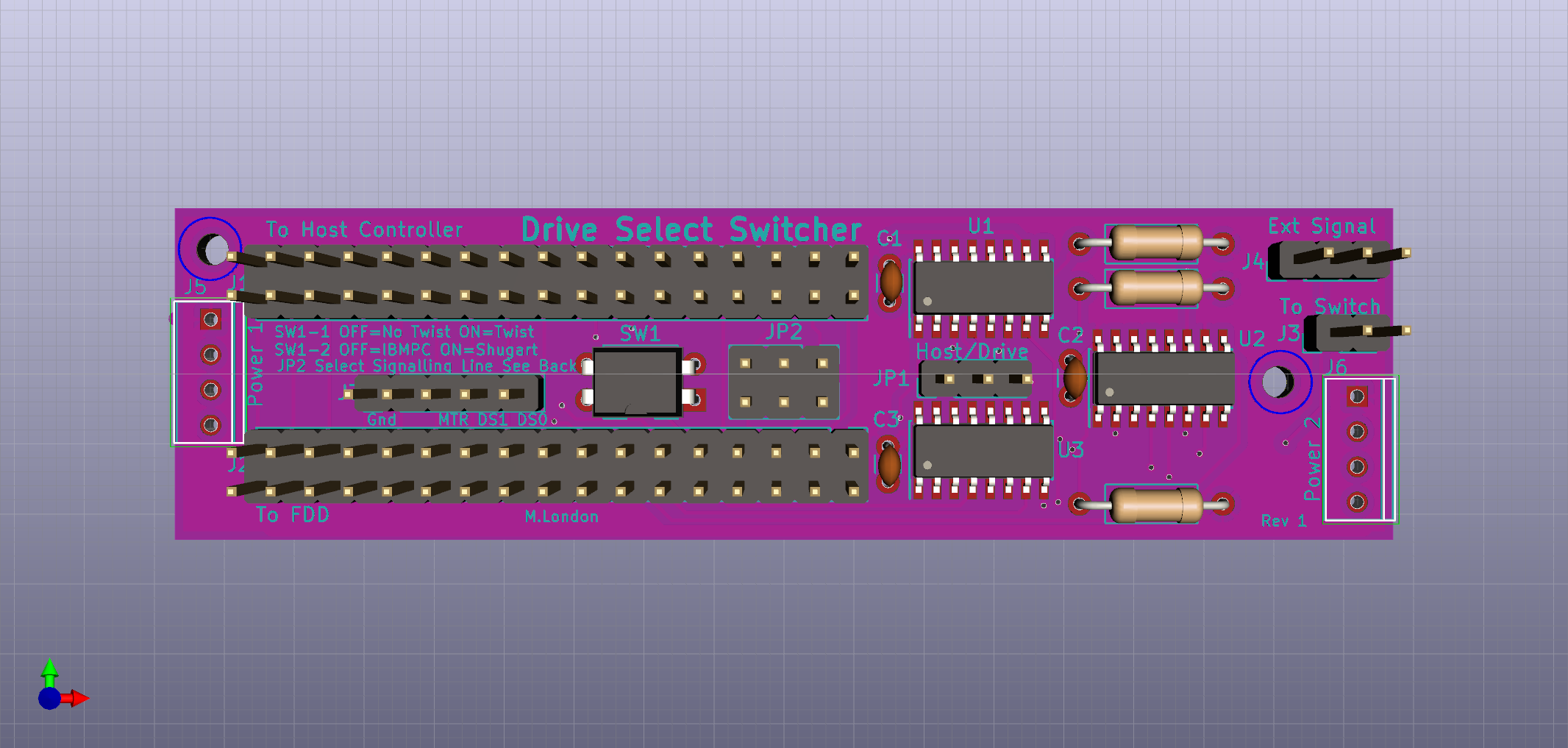
After giving this some thought, it occurred to me that there are some typically unused signals on most floppy cables, and depending on the controller, it might be possible to just use one of these lines to carry a "switch drive select 0 and 1" signal. What I came up with was this little board which does just that, using either one of two nominally unused signal lines on the existing floppy bus, or an external signal line.
Principle of Operation
The board can be used in one of two ways:
- If it's easy to put the board between the floppy controller and both drives (e.g. in a PC where both drives are internal), you can just use a single board, connecting one side to the controller, and connecting the existing floppy cable to the other.
- You can use two boards, one connected to the back of each drives and connect the existing floppy cable to the board instead of the drive
You connect an SPST switch to one board, set the jumpers to match your system, and away you go.
In practice, if you want to use one of the nominally unused signal lines (pins 4 or 6), you might want to snip/break that conductor between the controller and the drives, depending on how it's connected up. I've yet to trace out these pins on my machines, so I'm not sure which are actually used and which aren't. I'll try and post a list here as I get that information.
Features
- Works with 34-pin Shugart and IBM-PC type pinouts
- Can use (nominally unused) pin 4 or 6 on the existing interface to carry the switch drives signal, or use an additional wire
- Can work with a twisted or untwisted cable
- Can be used either in a pair (on each drive) or singly (between controller and both drives)
Installation
Single board
If you have a system where the floppy controller connects to both drives on single cable (e.g. controller---drive---drive, or controller---external-connector---drive), you can use a single board and connect it between the controller and the existing cable
- Set JP1 to Host (1-2)
- Set SW1-1 to Off (No Twist)
- If the system uses IBM PC type signalling (i.e. if the floppy cable has a twist before the last connector), set SW1-2 to Off (IBM-PC), otherwise set it to On (Shugart)
- Set JP2 for External Signalling (1-2, 5-6) unless you want to connect a switch on an external floppy connector (discussed later)
- Unplug the floppy cable from the controller and connect it to J2 (To FDD)
- Plug in the short 34-pin cable to J1 (To Host) and plug the other end into the controller where you disconnected the floppy cable. Pay careful attention to pin 1 (marked on the socket, red/blue/black stripe on the ribbon cable)
- Connect an SPST switch to J3 (To Switch)
- Connect a regular 3.5" power connector from the system's PSU to either J5 or J6 (Power 1/2) - it doesn't matter which
Two boards
In this configuration you install one board on the back of each drive and they signal to each other to coordinate switching drive select lines. Follow these steps for both boards:
- Set JP1 to Drive (2-3)
- Set SW1-1 to match the cable connected to the drive to which you are going to connect this board. Typically this will be Off (No Twist) on all Shugart type systems, and drive B: in IBM-PC systems, and On (Twisted) for drive A: in IBM-PC systems.
- If the system uses IBM PC type signalling, set SW1-2 to Off (IBM-PC), otherwise set it to On (Shugart)
- Determine which conductor you want to use for signalling between the two boards and set JP2 appropriately. This can be either pin 4 (INUSE) (1-3 5-6), pin 6 (DS3) (1-2 3-5), or an External cable connected to J4 (1-2 5-6)
- If you are using pin 4 or pin 6 on the floppy cable to signal between boards, you may need to cut the conductor between the controller and the first board. This will depend on the specific system and I hope to document this as I get the information.
- Unplug the floppy cable from the back of the drive and connect it to J1 (To Host) on the first board, paying attention to pin 1 location
- Plug in the short 34-pin cable to J2 (To Drive) and plug the other end into the drive where you disconnected the floppy cable (paying attention to pin 1)
- Connect an SPST switch to J3 (To Switch) to one of the two boards
- If you set JP2 for External Signalling, connect J4 on both boards together (technically you may only need pin 2, 1 and 3 are both Ground, which is on the floppy bus)
- Connect a regular 3.5" power connector from the system's PSU to either J5 or J6 (Power 1/2) - it doesn't matter which. If you have a 5.25" drive, it is easiest to get a splitter cable that accepts a 5.25" style plug and connects to both 3.5" and 5.25" type plugs. If you have a 3.5" drive, you can either use a splitter cable, or use the other power connector on the board (J5/6) to connect through to the drive with a short cable.
January 21st, 2020 - 16:36
This seems like a really useful project.
I use GOTEK clones and have a few machines in which I’d like to mount 3.5 / 5.25 floppy drives as well as the GOTEK. Your solution would be excellent.
May 12th, 2020 - 16:23
Hi, This looks very interesting. I, like you, use Gotek emulators on most of my machines (IMSAI 8080, SOL-20, OSI C4, Atari ST etc etc). I was searching around to see if anyone has designed a floppy switcher so I could flip between drives. A typical situation I would want to use it is like this. E.g. My IMSAI 8080 – there is a single 50 pin cable that comes from the FDC to dual 8″ shugart drives. Each drive has jumpers for drive number 0 or 1. However presently I have the 8″ shugart drives disconnected and instead the 50pin cable goes through a 50pin to 34 pin adaptor then to a Gotek and a 3.5″ drive (which mimics an 8″ drive). It would be great if I could switch between the two setups easily (Gotek+3.5″ vs Dual Shugart 8″). Could your board be modified to work in this situation?
April 4th, 2022 - 16:03
It’s still not quite in a functional state – I had a problem with the initial design and I’ve not had time to debug it properly. It sounds like what you’re looking to do is select between two pairs of drive select lines – what I’ve currently got isn’t really set up for that, but you wouldn’t need anything quite as complicated as I’ve got either.