Upgrading the V86P HDD Controller
Back in a previous post I set about reverse engineering the HDD controller, and one of the things I was able to work out was the pinout of the connections to the mainboard. In fact, I commented that this looked like a stripped-down ISA bus with only the necessary signals being routed through - a fact confirmed by the system interface IC on the controller. I think I mused at the time at the possibility of fabricating a board that fits where the existing controller goes, but contains an XT-IDE (for those unfamiliar, this is an open-source IDE controller for 8-bit ISA systems that allows the use of regular IDE/PATA drives). In my last post, I documented my work with the expansion bus and testing with a regular 8-bit ISA XT-IDE card - which worked perfectly, with the exception that the top 384k of RAM (normally available via EMS) has to be disabled because there were conflicts with the default ROM location of the XT-IDE's BIOS. Pulling the internal controller and relocating the ROM location should address this.
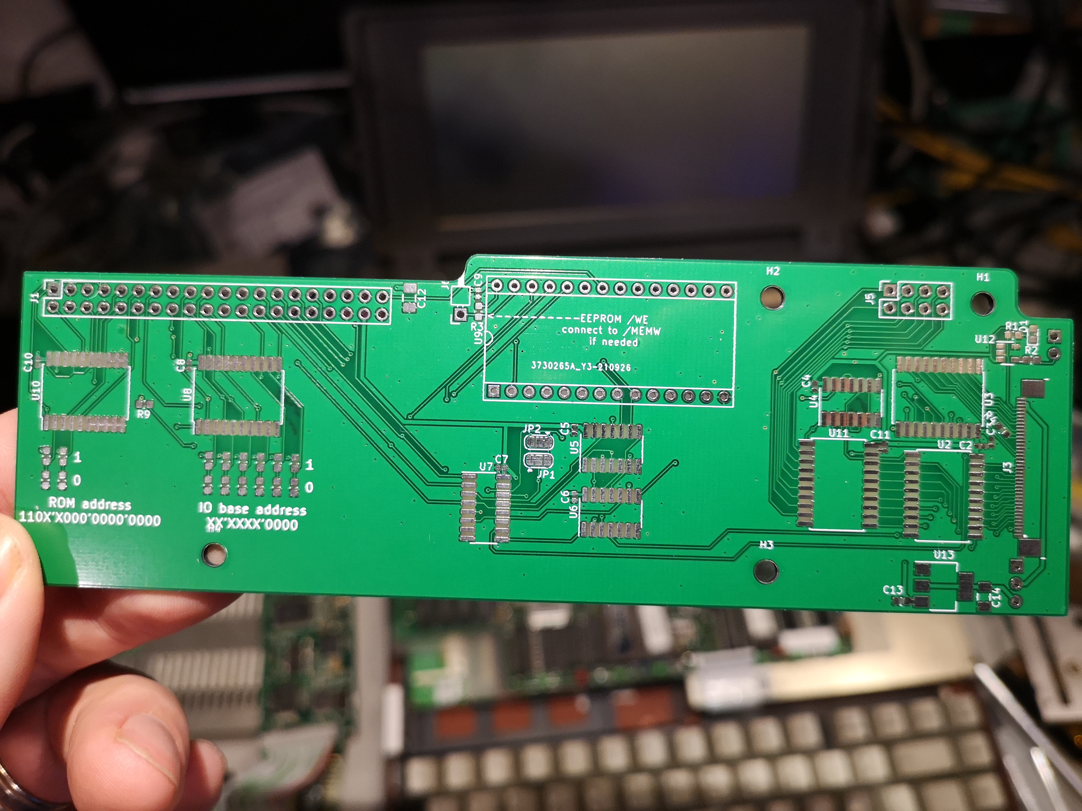
Having demonstrated that the XT-IDE did indeed work correctly, I figured the next thing to do would be to set about creating a replacement HDD controller to mount inside the system. All the signals required by the XT-IDE are present on the internal HDD controller headers on the motherboard, with the exception of /MEMW, and that's only required for firmware updates. If required, /MEMW could be pulled in from a jumper wire run down to a pin on the expansion bus header. Unfortunately, at this point, the V86P project ended up being shelved for a while and I never had chance to set about the process of creating a suitible controller board. However, unbeknown to me, @hennichodernich over on Twitter had seen my posts and been inspired to do a little tinkering with his V86P during COVID lockdowns - basically doing the same sort of tests as I'd done with an XT-IDE controller, and then proceeded to design, prototype, and build the internal controller PCB. He documented his process over on twitter and once complete, published the design over on github at https://github.com/hennichodernich/v86p-ide
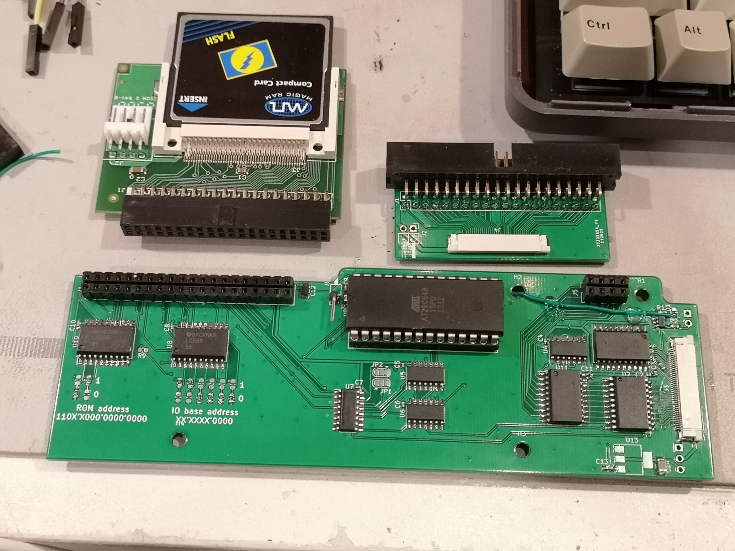
This was the perfect catalyst to get me back into my V86P project, so I set about getting a set of boards ordered based on his design - both the controller board, and the matching expander board (due to space constraints, it wasn't possible to fit a regular 40-pin 0.1" or 44-pin 2mm pitch header on the controller board so he used a 40-pin flat-flex cable. The flex board takes the flat flex cable and brings it out to either a 40-pin 0.1" (for 3.5" drives) or 44-pin 2mm pin header (for 2.5" drives). Parts were easily sourced from Digikey, with the exception of the EEPROM, which was hard to track down due to ongoing parts shortages. Luckily, I'd picked up a second set of XT-IDE parts without the PCB (thanks glitch!) with the intent of this project back before it was all put on hold, so I was able to use the EEPROM from that kit.
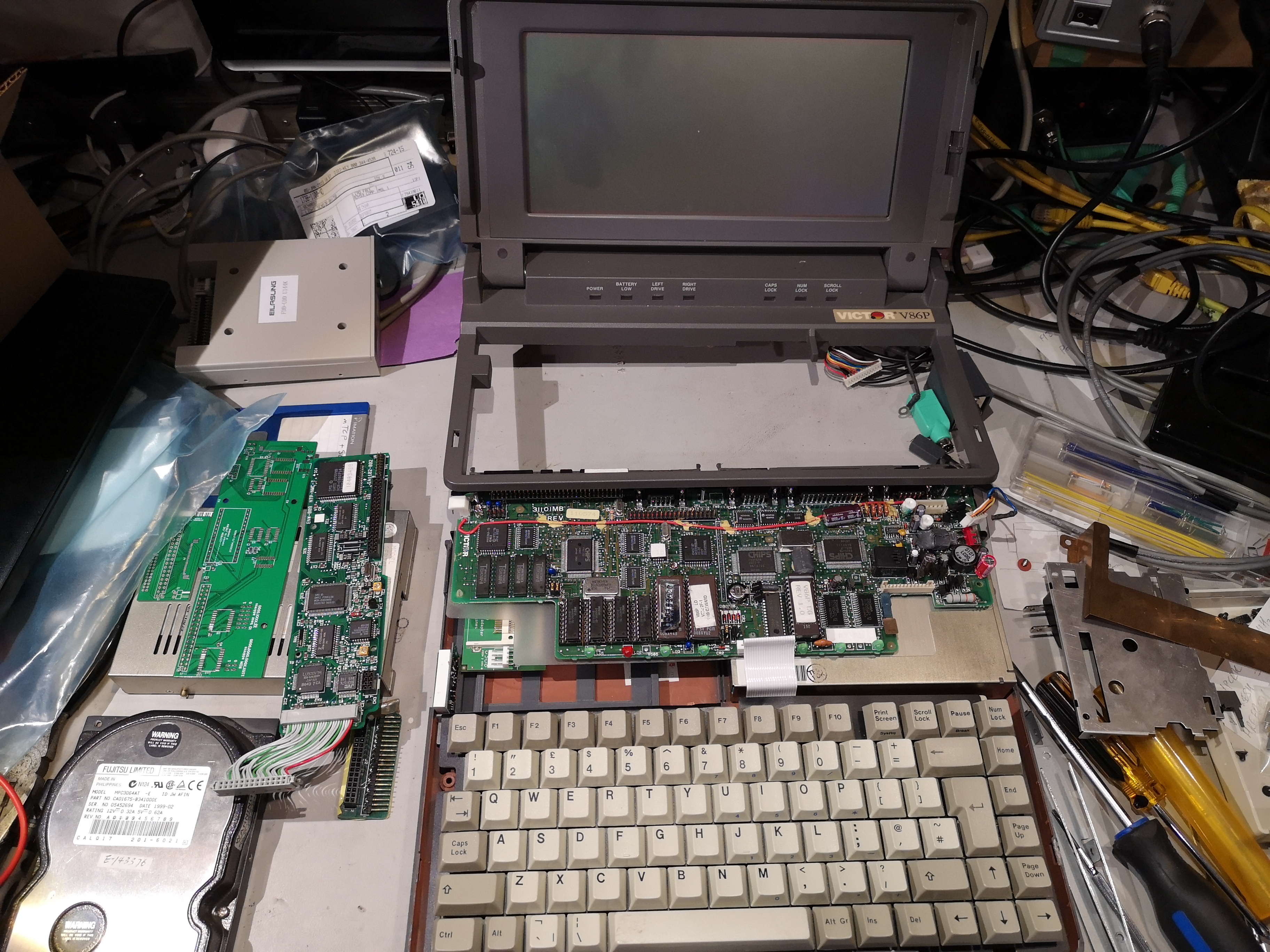
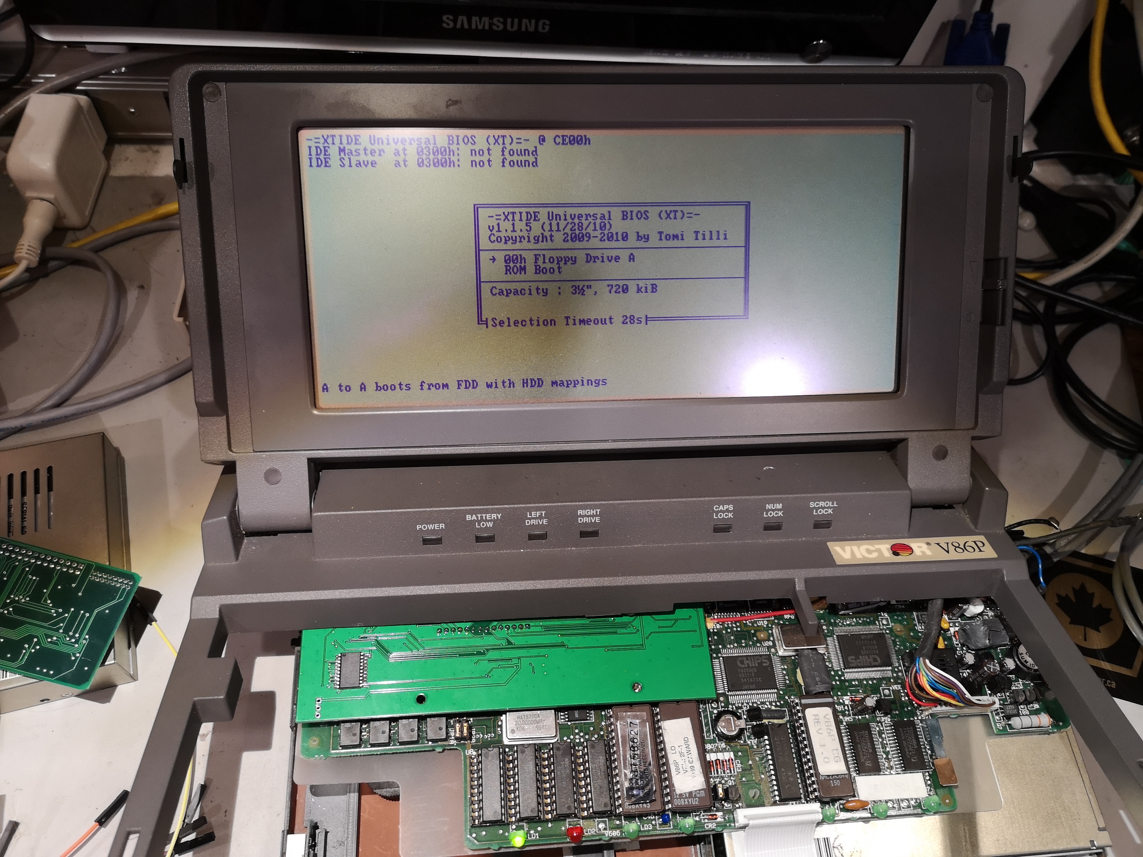
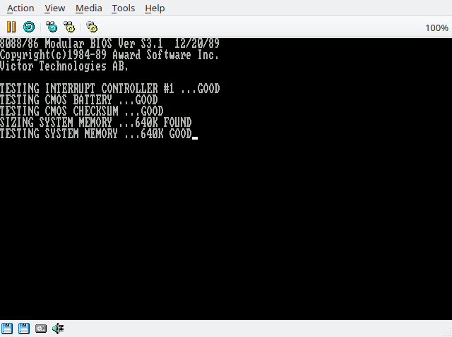
I ordered the boards from JLC PCB, who have decent pricing for prototype boards exceeding 100mm in one dimension (which tends to be the maximum dimension at the other fabs). I didn't feel confident soldering some of the SMD ICs myself, so I enlisted the help of another friend (thanks Joan!) to help with the assembly. She was able to solder up the SMD components for one of each board for me, and I was very excited to get the assembled boards back. I soldered in the headers to connect the board, and did a test fit to see if the EEPROM would fit in a socket - I wanted to be able to easily replace it in case there was ever a problem with a firmware update and it needed re-flashing externally. After confirming that fit, I went ahead and soldered in the socket and reinserted the IC. Opening up the laptop again, it was straight-foward to swap the existing 26-pin JVC controller for the new XT-IDE. For testing purposes, I just hooked it up to the same 3.5" IDE drive I'd used to test the ISA XT-IDE previously, along with a suitable power supply. Because the original controller had been removed, the new XT-IDE board was jumpered to reside at the same IO address as the old controller, thus preventing the issues with RAM overlap experienced previously. Powering on the laptop, it passed all POST checks and I was presented with the XT-IDE BIOS screen, and the system them booted from my external hard disk. Next steps - get something mounted internally.
After digging through my parts bin, I was able to locate a CompactFlash adaptor designed to plug directly into an IDE connector on a motherboard. This fit nicely onto the flat flex adaptor board, and it's possible to mount where the original hard disk is mounted, allowing the CF card to be accessible through the floppy drive hole in the side of the case. First thing to do was to test the adaptor board with a CF card and make sure it actually worked - this I did using an old VIA C3 mini-itx board I keep around for testing this sort of thing. Next was to get a suitable CF card - the ones I have to hand were either bad (why are they even in the parts bin?), or already being used for something else (like my A1200).
Whilst I was waiting for a suitable CF card to arrive, I ran across the 86Box project - it happened to come up whilst I was searching something to do with the V86P BIOS. It turns out that someone has implemented the hardware description for the V86P along with dumping a couple of sets of BIOS ROMs See here for details. This seemed like it might be a perfect testing resource for development - particularly if I wanted to work on a disk image with the V86P drivers and utilities.
Another thing I came across during searching was a Victor OEM DOS boot disk over on WinWorldPC - this contains a bunch of utilities originally shipped by Victor with these machines, so seems like a great place to start for an alternate hard disk image (it's a DOS 3.3 based setup, and 5.0 is a more friendly environment for a lot of things).
 Once my CF card arrived, it was time to write out a disk image. Unfortunately, 86Box doesn't currently support drive pass-through to raw block devices, only supporting disk images (one thing that occurs to me now is that it might be possible to jump through some hoops with FUSE to present a block device as a file - I might have to have a play with this). VMware workstation can do this, and that's how I'd created my original MS-DOS 5.0 hard disk install - connect the drive to my PC with an IDE->USB adaptor, connect that to a VM using a raw device map, and then boot the VM from the MS-DOS 5.0 install media from a floppy image. I did the same with my Victor PC-DOS 3.3 media and a CF device in a USB adaptor using VMware, then made a disk image of this for 86Box using dd. I created a new configuration in 86Box for a V86P, but then removed the JVC hard disk controller and added in an XT-IDE, attaching my new disk image to that. I then attempted to boot the system and it did indeed boot as expected - so this means I have a viable environment for testing without relying on physical hardware.
Now I had a CF card with what should be a bootable OS image, I tried plugging that into the real system and booting it - only to be met by an odd error message instead of booting the OS. Unfortunately, I don't appear to have made a note of the message, sorry 🙂 I tried the card in another real PC, and had a similar issue (this time I did snap a picture).
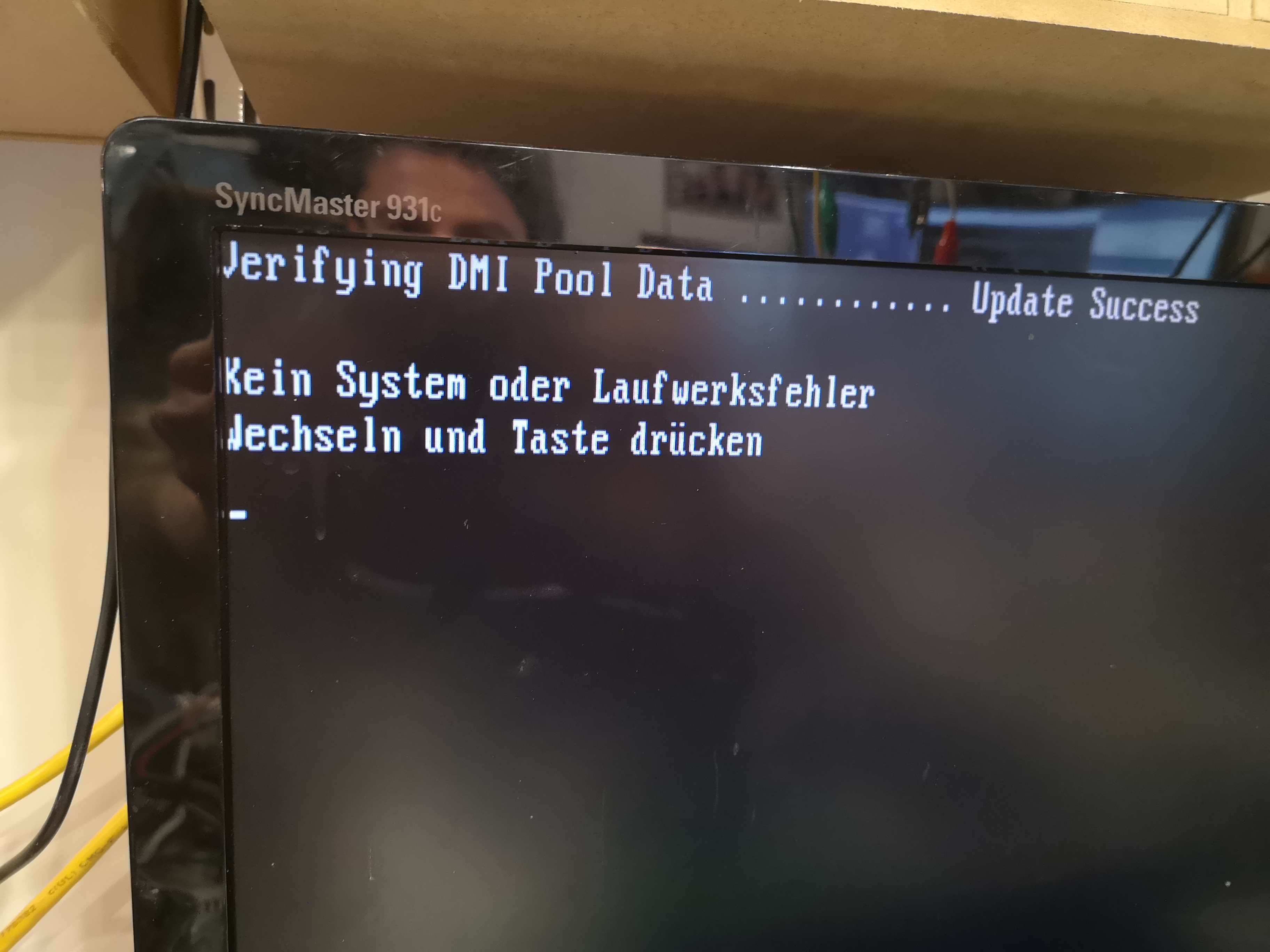
I eventually tracked down the problem to a difference between how Linux and the XT-IDE were detecting the CHS parameters for the CF card. Obviously as a flash device, it doesn't actually have Cylinders, Heads, and Sectors - it's all LBA addressing (where you just specify the address of a block directly), so accessing via C/H/S addresses results in a translation to an LBA block. When asking fdisk on Linux for the CHS values (1009/16/62), and then comparing to what the XT-IDE was detecting for the CHS values (993/16/63), I noticed they differed. After a bit of digging, I discovered you could force Linux to use specific values for a device. I don't remember the exact details (this is what happens when you don't make notes at the time, then wait a year or more to write up the post), but I think what I ended up doing was running the Linux fdisk command against the drive and going into advanced mode, in which you can then modify the values for number of cylinders, heads, and sectors per track for the device. Setting those to the values the XT-IDE was detecting meant the starting block of the partition would be in the right place - MS-DOS aligns partitions with the start of a cylinder, so a difference in one sector per track in the CHS values means the partition ends up being offset by 512-bytes in its location in the CF card.
Once I had a partition table on the device that looked to be based on the right CHS layout, I tried writing out my disk image again. This time, when I put it into the CF reader attached to the V86P it booted! The system felt responsive, and the only real thing of note was the delay in reporting free space when running DIR, which was expected.
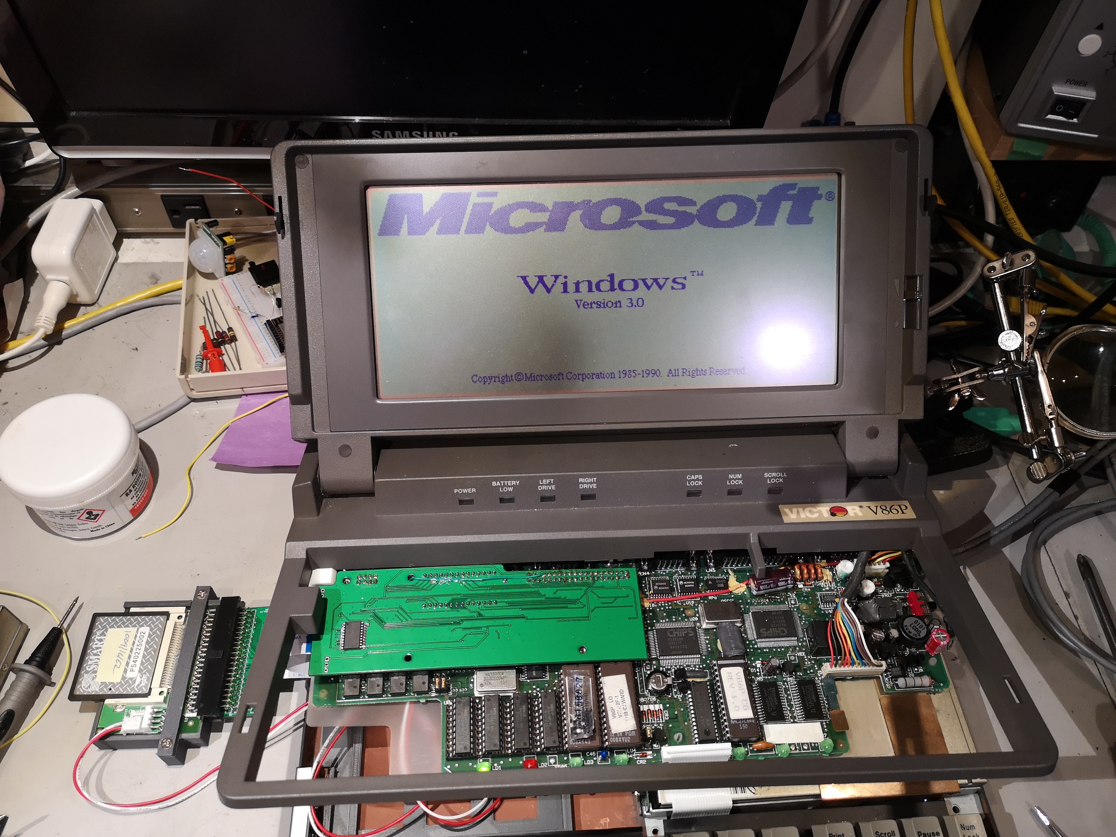 Now it was time for some real fun - I've got an 8MHz XT with a mono CGA display, and an easy way to copy files on and off without mucking about with floppies, floppy images, or serial links. It was time to try throwing some more software on there. The first thing to try was Windows 3.0 - this will still run happy in real mode, so runs on an XT, and has support for CGA's 640x200 monochrome mode. I ended up running the install process using a VMware VM as I described earlier, with the CF card connected as a Raw Disk Map - the only thing I had to do to get it working on the laptop was to re-run the setup utility to reconfigure the video adaptor to the correct CGA type (VMware doesn't do 640x200 CGA correctly). Unfortunately, I wasn't able to pin down a serial mouse (I was sure I had one somewhere), so I had to do everything with the keyboard. It's a bit slow, but Windows 3.0 is surprisingly usable, and the display is nice and crisp, if a little short vertically at only 200 pixels. If I'd had more blank disks to hand, I could've made a real set of install media and installed on the laptop itself (or rigged up a gotek in place of the floppy drive).
Having demonstrated that everything was working properly, the next thing to do was to set about mounting the CF card reader internally in the system. There were a couple of options for this - the first was to take a tray designed to fit in a 3.5" bay (either one for mounting a 2.5" drive, or a blanking tray used to fill an empty hot-swap carrier, and to mount the CF reader to that internally; the second was to print a custom mounting bracket on a 3D printer. The first option would definitely be the quickest - it would be trivial to just screw the existing mounting rails to a plastic tray and then stick the CF reader down inside it. The major down-side to this is that the CF card would then be inaccessible without disassembling the system. Whilst this wouldn't be any different to just installing a different hard disk, one of the big advantages of using a CF card is that it's easy to move it from one system to another in order to copy files on and off, and the case has a slot cut in the side for a floppy drive already, thus making it easy to get at something in that drive bay.
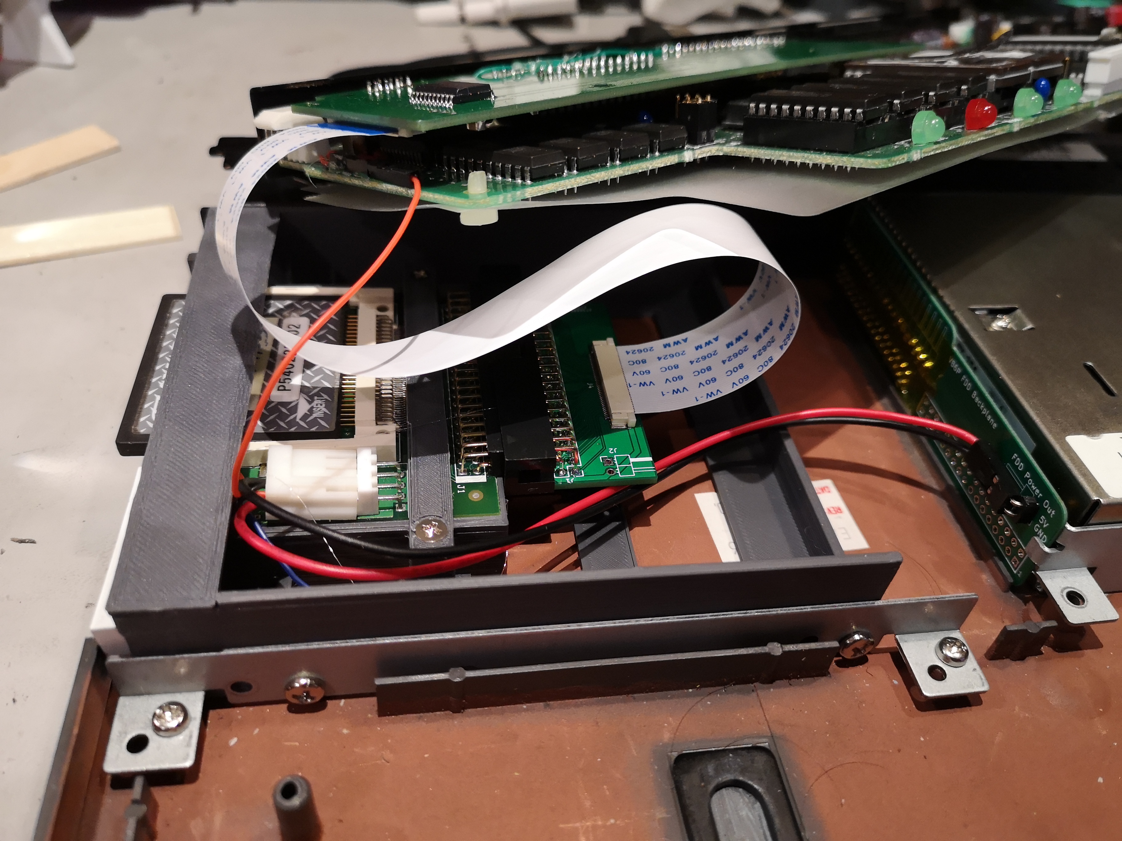 Documenting the process for creating the 3D model would be a whole blog post in itself (maybe I'll write that one up some time if there's interest), but in the end I created a model using OpenSCAD for a tray to which the existing hard disk mounts can be attached to secure it into the case. Attached to the outer tray is a box into which my CF reader will sit, with a friction fit (the reader doesn't have any mounting holes) and a bar that screws down over the top to provide some additional security (this is a laptop and it's likely to get bounced around). I also included a mounting bracket for the battery charge indicator, the details for which will be in a future post. The first print was pretty close, but did need a couple of monitor adjustments to make it fit; the second print fit perfectly, and I was very pleased with the end result.
The floppy opening is slightly recessed compared to the outermost edge of the laptop, and the CF card sits just slightly proud of the opening, allowing it to be removed and inserted relatively easily, whilst being recessed from the edge to prevent it being vulnerable to bumps and bangs. The battery indicator fits very neatly behind the cutout for the eject button, allowing all the bars to be visible (details on this will be in a later post).
 Having closed everything up, I'm very happy with the end result. The only thing I might do in future is alter the tray to have a front panel that blocks the empty bits either side of the floppy slot, so there isn't an opening through which bits of crud can get inside the case - an improvement on the original design.
One thing that did occur to be during this bit of the project was whether there might be enough space internally to include a floppy disk emulator like a Gotek or OpenFlops board. OpenFlops being of particular interest, as it would be theoretically possible to spin a board containing both the floppy emulator hardware and a CF card slot with flat-flex socket - thus neatly combing both into a single board that's designed to mount in the space available. It could even have the 34-pin header in the right spot to connect to the riser card, and take power directly from pin 1 on the header. The main issue there is the availability of the appropriate STM32 modules, which I know where in short supply a year or two back (and Gotek switched over to Artery MCUs instead) and I've not looked into seriously since then.
One other thing I ran across during my travels was the following ROM dump on archive.org: V86P HDD Controller ROM BIOS) - not entirely relevant to this post, but I'll include it here in case anyone reading this is working on the original drive controller.
Finally, here's a gallery of photos showing more details on the process from start to finish:


Leave a comment
You must be logged in to post a comment.