The JVC 26-pin Hard Disk Interface (Part 1)
As I've mentioned in a previous post, my V86P is the higher-spec model containing a 20MB hard disk. Back in the mid to late 1980s, IDE was still relatively new and most systems were still using ST-506 interface drives, albeit using RLL rather than MFM to increase data rate and capacity. For example, I remember the Viglen Vig II 16MHz 286 we bought as our family PC back in '88(or so) had a 40MB RLL drive. Laptop form-factor systems were also relatively recent, with the floppy-based Toshiba T1100 being released in 1985 and the hard-disk enabled T1200 in 1987. Obiviously desktop drives of the era weren't ideally suited to laptop use, at that time 5.25" half-height was the dominant form-factor. The ST-506 interface also required two separate cables connecting the drive to the controller: a 34-pin control cable on which drives could be daisychained, and a 20-pin data cable from each drive directly back to the controller. These connectors alone take up almost 3.5" of space along the edge of the HDD logic board, and that still leaves power, which makes developing an alternate interface fairly logical.
JVC approached these issues by developing a hard disk in the same 3.5" form-factor being used by floppy drives, and a custom 26-pin connection back to the disk controller. Based on what I've found on-line, this series of drives was used in a number of portable systems, including:
- Data General One Model 2T
- Epson PX-16
- Epson Equity LT
- Epson Portable PC (Q150A)
- GRiD 1520
- GRiDCase 3 Plus
- Sharp PC-7200
- Toshiba T1200
- Victor V86P
- Wang WLTC Laptop
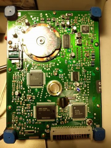
The drive construction is also clearly designed for use in a portable system, consisting of an outer housing with four rubber shock-mounts, one on each corner of the drive unit inside. At first, I thought this might have been specific to my laptop, but it seems that drives in other systems were also constructed the same way, so I assume this was part of the JVC design.
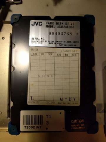
According to this post from 2001, an attempt was made to contact JVC to get information on the JD-3824G. From this communication we know that this series of drives was discontinued around 1991, and were an OEM product manufactured for use by laptop manufacturers. We also have the interface pinout (listed below), and the following drive specs:
- Capacity: 20MB
- C/H/S: 615/2/34
- Spindle speed: 2597rpm
- Encoding: 2,7 RLL
- Data transfer rate: 7.5Mbps
- Average seek time: 78ms
- Power rails required: +5V, +12V
Pinout for JVC original interface (26 pin)
| Pin | Name | Function |
|---|---|---|
| 1 | GND | |
| 2 | /READ | -Read Data |
| 3 | GND | |
| 4 | /WRITE | -Write data |
| 5 | GND | |
| 6 | RESERVED | Reserved |
| 7 | /SELECT | -Drive Select/+Power Save |
| 8 | /SHIP_READY | -Ship Ready |
| 9 | GND | |
| 10 | /WRITE_GATE | +Read/-Write control |
| 11 | /MOTOR_ON | -Motor On |
| 12 | /HEAD_1 | Head Select(+Head 0/ - Head1) |
| 13 | /DIR_IN | -Direction In |
| 14 | /STEP | -Step |
| 15 | /WRITE_FAULT | -Write Fault |
| 16 | /SEEK_COMPLETE | -Seek Complete |
| 17 | /SERVO_GATE | -Servo Gate |
| 18 | /INDEX | -Index |
| 19 | /TRACK_0 | -Track 000 |
| 20 | /READY | -Drive Ready |
| 21 | GND | |
| 22 | +5V | +5 |
| 23 | GND | |
| 24 | +5V | +5 |
| 25 | GND | |
| 26 | +12V | +12 |
From this site, I've got a list of other JVC drive that probably have the same interface, but they give some more drive paremeters which are useful to know:
| Model | Cylinders | Heads | Seek Time (ms) | Interface | Encoding | Capacity (MB) | 12V-Peak (A) | 12V-Avg. (A) | 5V-Peak (A) | 5V-Avg. (A) | Depth (mm) | Width (mm) | Hight (mm) | Weight (g) |
| JD-3806M | 2 | Unique | MFM | 5 | ||||||||||
| JD-3812M | 2 | Unique | MFM | 10 | ||||||||||
| JD-3824L | 615 | 2 | 68 | Unique(26pin) | RLL | 20 | 0.44 | 0.16 | 1.2 | 144.3 | 104.6 | 28.8 | 535 | |
| JD-3824R | 2 | Unique | RLL | 20 | ||||||||||
| JD-3824T | 615 | 2 | 65 | Unique(26pin) | RLL | 20 | 0.46 | 0.12 | 1.2 | 144.3 | 104.6 | 25.4 | 510 | |
| JD-3824TA | 615 | 2 | Unique | RLL | 20 | |||||||||
| JD-3848H | 615 | 4 | 45 | Unique | RLL | 40 | 0.6 | 0.12 | 1.3 | 144.3 | 104.6 | 31.4 | 575 | |
| JD-3848HA | 615 | 4 | Unique(26pin) | RLL | 40 |
So based on all that information, it looks a lot like a modified ST-506 interface with TTL signalling for /READ and /WRITE rather than differential pairs, and a handful of additional signals that seem a lot more suited to a disk installed in a laptop. I can confirm from playing with my system that the disk does not spin up until the controller initializes it, and the head automatically parks after a couple of seconds of inactivity (I'm assuming that's what /SHIP_READY is to signal). Using TTL signals for /READ and /WRITE was probably deemed acceptable because you weren't going to have more than one hard disk in a laptop, and the disk was going to be mounted very near the controller due to space constraints so the system didn't have to cope with the long cable lengths the ST-506 spec permits (up to 20'). I'm also guessing the /SERVO_GATE has to be asserted in order for the drive to act on /SEEK. The Reserved pin probably isn't used, but it's worth checking to confirm.
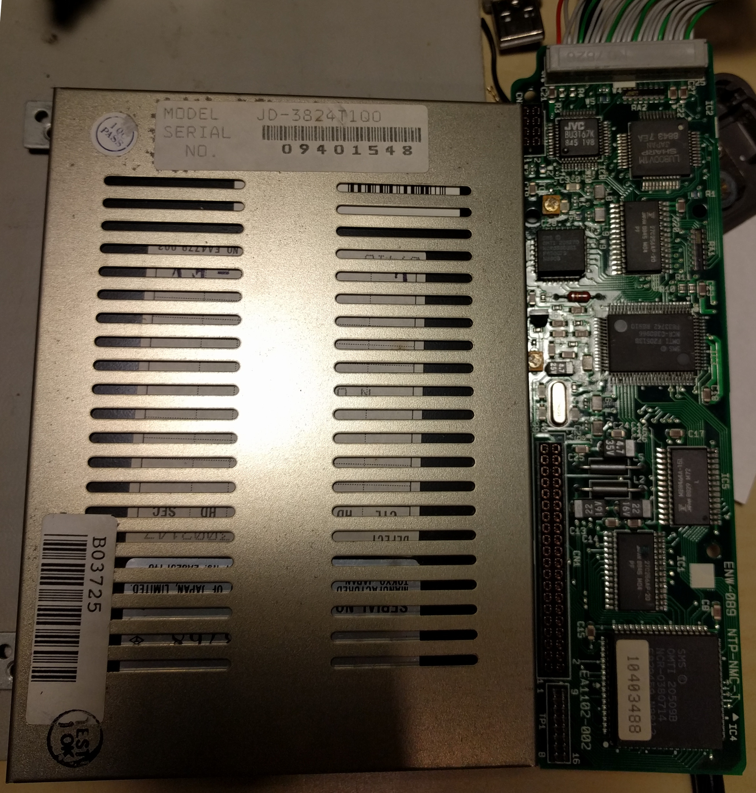
From a drive emulation perspective, it's important to identify how the data is encoded when reading from/writing to the disk. Given the sparsity of information from JVC, the natural thing to do would be to go in the opposite direction and look at the disk controller. In the V86P, this is a small daughterboard that plugs into a pair of pin-headers on the motherboard. The 26-pin disk interface cable is then attached to this board, with a connector on the other end that plugs into the drive.
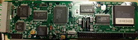
At first glance, there's not much on the board, but by the late 80s this was all pretty standard stuff found in a large number of desktop systems. The three OMTI chips on the board looked promising, and I do recall coming across OMTI chipsets on disk controllers in the past. Googling the part numbers (20509, 20513, 20527) didn't get me terribly far, but once I started looking at datasheets on bitsavers I was able to find several that sounded promising, with names like "Programmable Data Sequencer" and "2 of 7 RLL VCO Encode/Decode Chip" even though the model number didn't line up with what was on my chips. Included in that archive were some sales brochures, highlighting the range of disk controller ICs. Right at the top of the first page was a promotional photo showing the chips, and there amongst them were the 20509, 20513, and 20527! Skimming through the rest of the sheet showed no other mention of them though, but it did mention several chips for which there were datasheets. I started reading through the "OMTI 5027 2 of 7 RLL VCO Encode/Decode Chip" datasheet on the principle that if my drive is indeed RLL, the OMTI chip used on my board is probably similar. Imagine my surprise when I got to the pinout page and it showed the silkscreen on the package as "OMTI 20527"! Based on this discovery, I was able to identify (and get datasheets for) almost all the ICs on the controller:
- OMTI 5090 (marked 20509B) - IBM PC Bus Interface
- OMTI 5055 (marked 20513B) - Memory Controller and Programmable Data Sequencer
- OMTI 5027 (marked 20527D) - 2 of 7 RLL VCO Encode/Decode Chip
- Sharp LU800V1M - CMOS 8-bit Single Chip Microcomputer (ROM-less) (SM803/A without ROM)
- Fujitsu MB8464A-15L - 8x8k 150ns SRAM
- Fujitsu 27C256AP - 8x32k CMOS PROM
- JVC BU3167K - Unknown
Given this is a JVC interface we're dealing with, I suspect that the JVC chip is handling the signals that aren't there in the ST-506 interface, such as Power Save, Ship Ready, Motor On, and Servo Gate. I think one of the next things I'll look at doing is ringing out the connector and seeing which lines are present on the pins of that IC.
The use of the OMTI 5055 and 5027 would seem to confirm that this is using standard 2,7 RLL encoding with ST-506 signalling - why else use off-the-shelf chips that implement it? That should make emulating the drive a reasonable goal (although probably not one for this challenge). I talked to David Gesswewin, developer of the MFM Emulator at https://www.pdp8.net/mfm/mfm.shtml and whilst his emulator doesn't currently support RLL, he said we could take a look once I've got some more information and some hardware to work with so long as I'm happy to write some code.
I've put together a simple breakout board with a pair of 26-pin connectors wired together, and a 20-pin header in the middle bringing out the 16 signal lines to allow for probing with a scope or logic analyser. I've also put a provision on the board to take +5V and +12V inputs and jumpers to select whether the drive 26-pin header gets power from the host or the breakout board for each of the three power lines. The PCB is away being manufactured, and fingers crossed will show up in a week or two.
The next things I plan to look at are:
- Try and identify the motherboard header pins that connect to the OMTI 5090 - I know what the 5090 pinout is, so that will let me identify the pins on the motherboard
- Try and identify a partial pinout for the JVC BU3167K based on the 26-pin header and surrounding chips
- Build up and check the breakout board when the PCB arrives
- Hook up a logic analyser and try to get some traces to confirm the hypotheses abou ST-506 signalling and the proprietary signalling
April 10th, 2017 - 04:48
Nice discovery and analysis. Surprising to think that a relatively common alternative to ST-506 could be so “unknown” – even I had never heard of this before.
September 26th, 2017 - 10:11
Great information.
I too have such a HD which is part of an “Accura 101” labeled system formerly sold by the German department store chain named “Karstadt”.
It seems to be a V86P CG based “clone” which was build in 1990-08.
The BIOS is labeled:
Chip U23 = V86P CG Rev. 1.0
Chip U17 = 101 QCI Q3A (L)
Serial Number of the HD is:
06538619
Unfortunately the HD has an error since a few days. It starts spinning during boot up but then stopped and didn’t spin any longer. So I’m actually not sure what’s the reason.
Any idea to find the problem is warmly welcome.
January 30th, 2018 - 18:40
I’ve got a T1200 (in bits) with a drive of this type; I’ve dumped the firmware ROM on the hard drive controller daughterboard. From a quick look-over with a disassembler, I think it’s Z80 machine code. Any use to you?
March 14th, 2018 - 19:41
Now I’m intrigued by that daughterboard, specifically by the two connectors to the laptop’s motherboard.
On the images, there seems to be a smaller one, presumably for supplying the board and harddrive with power. The large one seems to have 40 pins. Is it possible, that it is in fact an 8bit IDE, or XTA, connector? Could you somehow check that, e.g. by probing with the logic analyzer and comparing the signals to the XTA pinout?
I know JVC has manufactured 2.5″ XTA compatible IDE hard drives. So maybe this might be an earlier iteration, with the disk controller on a daughterboard.
April 17th, 2018 - 08:36
If you have a look at the follow-up post, I did ring out the headers – they’re essentially a stripped down ISA bus, with the smaller connector being the data lines, and the larger one address and other signals. Drive signalling looks to be a slight modified ST-506 configuration using all TTL (no differential signalling for read/write)
November 11th, 2018 - 12:38
I’ve got a Nixdorf Laptop 8810/15 with a JVC JD3824r00-1 hard disk. Maybe the controller or the disk has an issue because the disk does not spin up. So I removed the disk to test ist. Can I power up the disk with a power supply only?
February 14th, 2019 - 08:20
The drive won’t spin up with just power applied – it was obviously designed with laptop power consumption in mind. You need to bring pin 11 low (/MOTOR_ON) in order to tell the drive to spin up. I don’t recall at this point if you also need to assert /SELECT (pin 7), but I don’t think you do. You need to apply power to both 5V pins as well as the 12V pin on the connector in order to get it to work.
December 24th, 2018 - 13:21
I just try to bring an old portable 386 “Nixdorf Computer 8810/20′” back to life and “found” the 40MB Drive. If I get far enough, I will need the setup data.
Thanks for the good work.
October 7th, 2020 - 10:44
Hi – Did anything ever come of trying to sort out the 26 pin drive emulation?
I have a Wang WLTC with a dead JVC drive, I’d love to be able to pop in a emulated drive so the beast will boot up.
February 5th, 2021 - 08:55
Not yet – things got busy and I’ve not really had much time to work on this particular project. The guys over at https://drem.info/ have a working drive emulator that does JVC 26-pin now if you want an off the shelf device, although it’s a bit on the pricy side for me
January 31st, 2021 - 12:04
Thank you for this information, which helps with resurrecting a Tandy 1400 HD. The 20 MB Alps drive has this configuration, including the 26-pin header and daughter-board FDC.
September 10th, 2021 - 03:38
Thanks for the info. I’ve just pulled one out of a Toshiba 1200 and was intrigued.
February 24th, 2022 - 06:56
Hey just to let you know I had the same drive (with cage) in my Toshiba T3100/20.