Retrochallenge Roundup (and a quick JVC update)
Well, it's the final night of RetroChallenge, so it's time for a closing post. As I'd expected, I didn't get anywhere close completing my goals, with lack of time being the age-old excuse. However, it was still a very productive project and I plan to keep pressing on and making semi-regular posts. Hopefully I can keep the momentum going even through RC is over for another 6 months. Although I didn't get a wiki up and running to store the information I was gathering, it's all up on this blog - so that's a start as far as making it available is concerned.
Other key milestones:
- I hacked together a working PSU for the V86P - learning a lot about switch-mode PSUs in the process
- I reverse engineered the output stage of the original PSU, using photos and some measurements being taken remotely, and captured the result as a kicad schematic
- I'm most of the way through a PCB layout for the charging section of the PSU, which will provide all the necessary voltages to the V86P to run and charge the NiCd pack given only a sufficiently beefy 8.5V PSU. The missing piece is finding a case I like, then I need to tweak the board dimensions to fit
- II got the V86P running with both its internal HDD and FDD
- I found datasheets for most of the key ICs in the system
- I'm about half-way through mapping out the pinout of the hard disk controller to motherboard interface pinout
- I confirmed the pinout of the 26-pin JVC interface
- I identified the SHIP_READY and SERVO_GATE lines as signal that the heads were parked and a sector index respectively
- I identified that DOS sees a 4 head disk with 512 byte sectors, but the disk itself only has one head select line - possibly there's some logic for splitting 1k sectors into two logical heads - developing some basic C routines to call BIOS int13h
- I've confirmed I can read the ECC blocks from the data block via DOS int 13h calls, which should make reverse engineering the polynomial used by the controller relatively straightforward
- And lastly, which I'm going to cover below - I think I've finally confirmed the disk is storing 2,7 RLL encoded data
I was able to borrow a DSO from a friend (thanks Daniel!) This allowed me to take a look at the signal on the /READ and /WRITE lines of the controller, with the hope of confirming what my little USB analyzer was showing. The result is as follows:
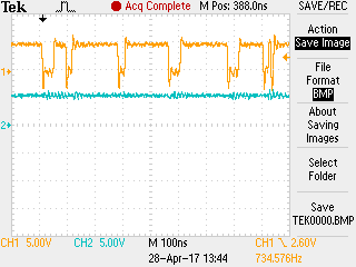
Read
Write
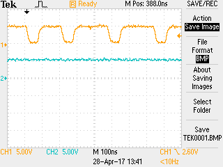
Looking at the traces, this looks like the read and write pulses are about the same width, with read being slightly shorter, and on closer examination, not quite so square. I suspected the issue might be the cable length between the logic analyzer and the break-out board. I shortened the cable as much as possible and ran another read test. This yielded the following result:
This looks a lot better, and has the regular pulse chain I was originally expecting to see.
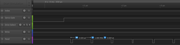
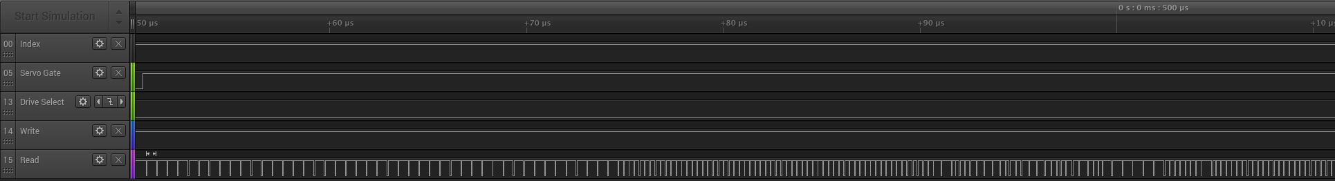
The datasheets for the OMTI 5055 and 5027 recommend using a value 0x33 for the inter-sector gap (and pre-index and post-index gaps) on RLL encoded drives. When you encode 0x33 using the 2,7 RLL code OMTI (and most other disk vendors of the time) used, you get 00010000 - which gives a repeating pattern of one pulse, then seven periods of nothing, then another pulse. That's exactly what that trace appears to be.
Following the inter-sector gap, we get an ID pre-amble of 0xFF, repeated several times (the exact count is up to the controller programming). 0xFF encodes as 10001000, so you get a pulse then three periods of nothing, followed by another pulse. Following that is an ID sync byte of 0x62 (which is 0010000001000100), then a marker byte of 0xfe (1000100010000100), then finally the sector data.
So as my parting image, here's what I saw when I looked at a trace, starting at the beginning of a sector - just compare it to what I described above:
August 24th, 2017 - 09:17
Fantasic work. I have a old Zenith supersort SX which needs a hard drive thats impossible to get anymore. If a interface of some kind could be made to replace the drive with a CF card like they have done for IDE drives it would be great and I could get this old Zenith working as it used to do before the drive packed up.
November 15th, 2017 - 01:22
Please take a look at DREM https://www.drem.info/
It emulates all sorts of MFM & RLL HDD’s including 26pin JVC models.
26pin JVC is a recent development and 26pin HDD header is not listed on web site yet, but I have it working with EPSON Equity LT in my lab now!
December 2nd, 2017 - 13:13
Thanks – I’d actually come across your project thanks to the TRS-80 Trash Talk podcast. Seems simple enough to deal with based on the chipset, although there’s clearly more to the signaling. I’m still hoping to get this all up on a wiki so anyone else with these drives has the information – would you be interested in contributing once I get that up?
I’ve got more to write up, it’s just finding the time 🙂 For this machine, I’m actually thinking replacing the controller with an XT-IDE based design and a CF card is the way to go
February 4th, 2018 - 01:34
Matt,
I truly interesting project. I have quite a few Toshiba laptops that use this interface. T3200, T3200sx, T1200 to name a few. What you are doing, I was hoping to do, but work and family commitments prevent this at this time.
I use the XT-IDE with several other vintage computers. It’s clearly the way to go, for cheap, reliable storage.
I follow your progress with enthusiasm.
Cheers, Martin