The JVC 26-pin Interface – Part 2
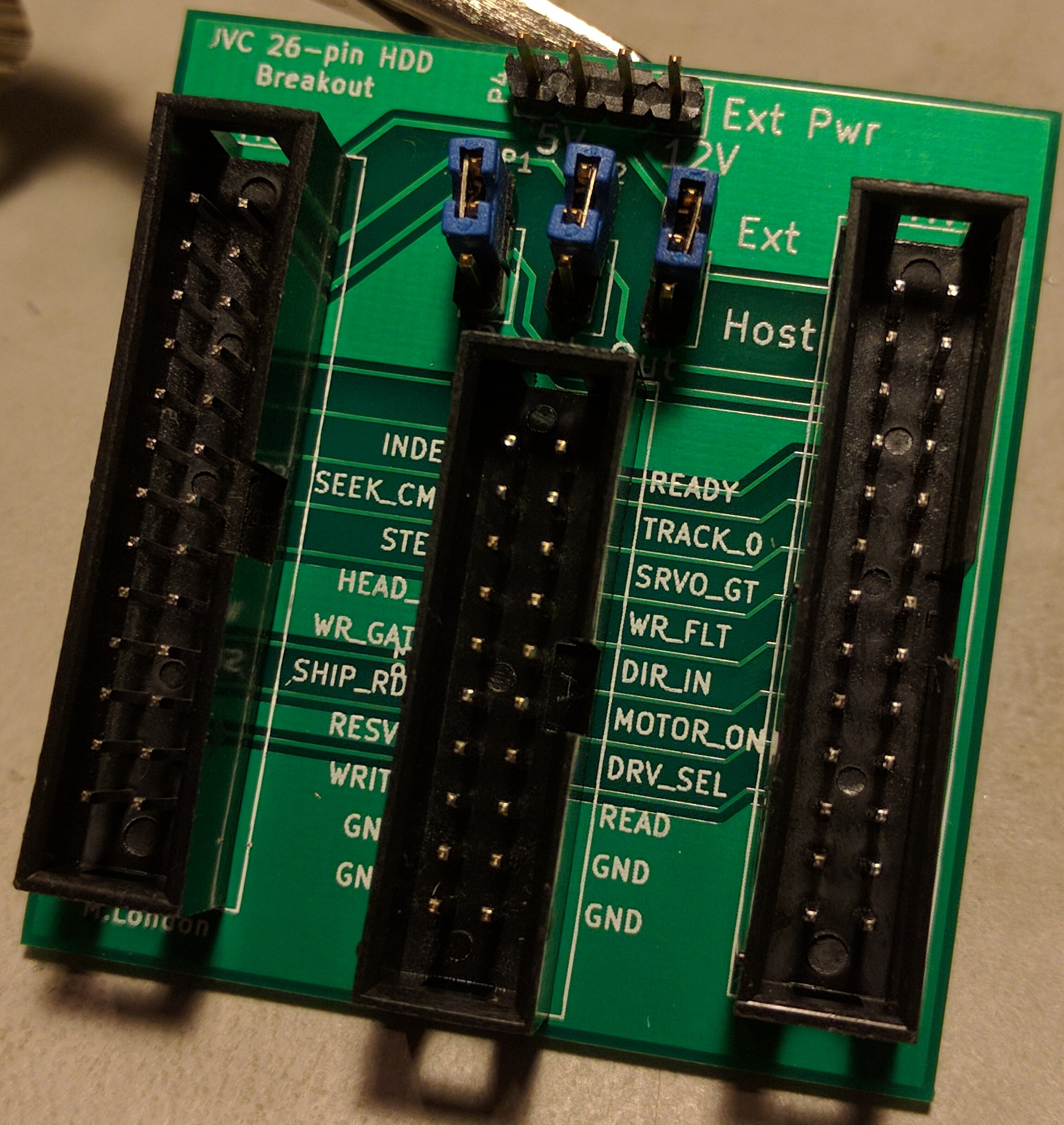
Welcome to the second part of my adventures with this slightly unusual hard disk interface. The more I dig, the more questions I raise - it's certainly good for raising the overall feeling of confusion. I think overall I'm making progress, but I'm still a long way away from even considering disk emulation (which was the original aim). As a quick recap of my previous posts - I designed a breakout board which brings the 16 lines of the 26-pin interface that aren't power or ground out to a pin header, along with support for supplying external power to the drive. I also got a power supply working so the laptop can run under its own steam, with both hard disk and floppy drive working correctly. I've got datasheets for most of the chips on the controller, and they look to be a standard ST506/412 RLL chipset, although with a few subtle differences and a mystery JVC chip - I've been reading through those and generally learning more about MFM than is probably necessary in 2017, but hey, isn't that what this hobby is all about?
My breakout-board PCBs showed up from Elecrow before Easter, but without the headers to build them up, they just sat on the side, mocking me with a minor error I made with the silkscreen. I got my act together and ordered the appropriate parts, and sure enough a box appeared from digikey that I picked up on Monday morning. It didn't take long to get one of the boards made up, complete with a little dremmeling of the socket for the host connection - the method of keying used on the drive connector involves a fat lug on one side and a thin one on the other, with matching cutouts on the socket. That was easily fixed with a sharp knife and dremel. Before connecting up the drive, I did a continuity check for the host connector through to the drive connector to make sure I didn't have any lines crossed. With that check done, it was just a matter of plugging in the disk and powering on the system - which worked perfectly.
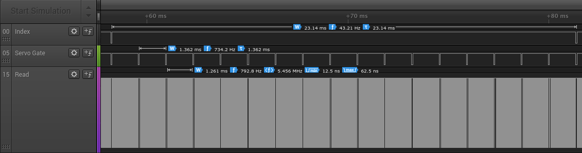
With that in place, I could hook it up to my cheap little USB logic analyser and take a look at what's going on. I plugged it in, turned on the laptop, setup the inputs, started a trace, and ran "DIR" - lo and behold, a trace appeared! Now, with all 16 channels, the capture rate is reduced (limited bandwidth over a USB2 connection), so I wasn't going to be able to see anything meaningful on /READ, but the various handshake lines are fair game. At first glance, my assumption about /SHIP_READY was correct - it goes low when the heads are parked, and high again when the disk is accessed. The time from one /INDEX pulse to the next is 23.14ms, which works out to 2593rpm - pretty close to the nominal 2597rpm of the specs I found.
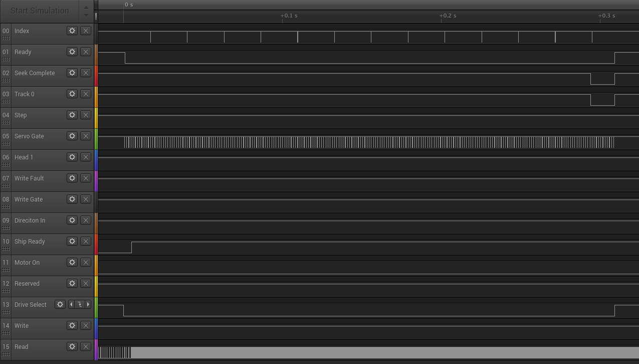
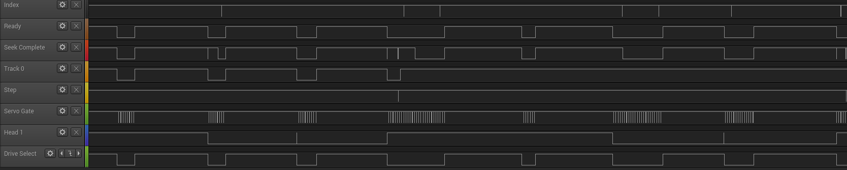
Drive Select, Ready, Track 0 and Seek Complete all behave as expected. Motor On is low the whole time, but with disk powerdown disabled - that makes sense. The disk doesn't spin-up immediately on power-on, so I assume when this line is high the drive will spin down. The thing that jumped at out me however is the /SERVO_GATE line - when /DRIVE_SELECT is asserted, there appear to be regular short pulses on /SERVO_GATE. Comparing /INDEX and /SERVO_GATE, there is a pulse on /SERVO_GATE at the same time (and of the same duration) as a pulse on /INDEX. There are 16 additional pulses on /SERVO_GATE at regular intervals before the next index pulse. This looks a lot like a sector index, and would be consistent with a standard 17 sectors per track. The next thing to do would be to try and follow that line on the controller and see where it goes. A few minutes with a multimeter and it's being fed into a terminating resistor pack, and on to the SECTOR/AMF pin of the 5055B data sequencer. From the 5055B datasheet: "This Schmidt trigger input can be used for either the Sector line of a hard-sectored drive, or the Address Mark Found line from a soft-sectored ESDI drive." This would confirm it's a sector index mark, and the drive is indeed 17 sectors per track, rather than the 34 listed in the specs I found.
The hypothesis that the drive is 17 sectors per track is an interesting one. I have no reason to believe the track count is incorrect, and there is only one head select line which would indicate only 2 heads. 615 cylinders of two heads and 17 sectors, with a capacity of 20MB calculates out at 1k sectors. Looking at the data-sheet for the OMTI chipset, this would be supported by the chipset, and the FAT filesystem also supports 1k sectors, but that's an odd sector-size for a PC, where 512-bytes is the norm (at least until recently). Time to see what DOS thinks about the disk. Back in the 80s, we (like a lot of other people) had Norton Utilities. I have fond memories of using the sector editor to figure out how the school "authorized disk" system worked, and authorizing my own disks (shh - don't tell my old head of IT - Mr.C - if you're reading this, sorry!) NU includes a Disk Information utility (DI), that gives you all sorts of useful information about the disk and filesystem. It didn't take much work to put that on a floppy, boot the system up, and see what DOS thought about the drive.
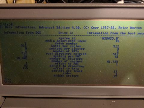
Now look at that, DOS thinks the disk uses 512-byte sectors. One of the things I came across when reading the ST-506/412 documentation was the presence of at least one Reserved line that was later used as an additional head-select bit, doubling the number of possible heads on a drive. There is a pin on the 26-pin interface labeled as "Reserved" in the JVC information, so the next thing to check was whether that pin was being used as another head-select line. However, checking this meant being able to read from a sequence of different heads. My first thought was to use Norton Utilities, but that would mean manually selecting a sector to read, then capturing that read, and repeating that for each head. It would be far more useful to have an application that read from specified sectors in a given order, that way I could just capture the read operations at once. It's been a long time since I did anything with BIOS calls, but I did remember it was possible to read sectors from disk with a BIOS interrupt call. Off I went to read up on BIOS int 13h.
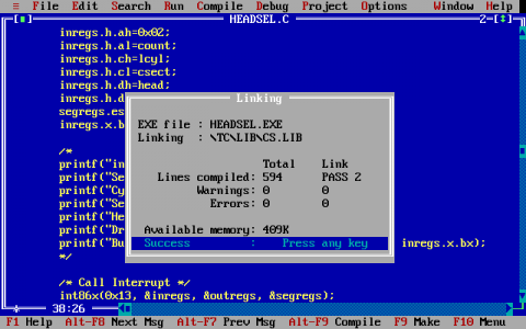
BIOS int 13h provides disk services, allowing (amongst other things) reading and writing specified sectors from a specified disk. At first I thought about doing something in x86 assembly and either assembling it on my Linux desktop, or using DEBUG. Then I thought about in-line assembly in C, which is more comfortable ground for me - I never did get very far with x86 assembly (I could setup the registers and make the interrupt call, but things like loops would require a bit more reading). That got me looking for a suitable C compiler and some example code. It didn't take long before I had Borland Turbo C++ 1.01 (which is what I used back in the mid 90s) set-up under dosbox, and a C function that set up the necessary registers and made a call to int86x(0x13...). Unfortunately, CHS disk access in dosbox via int 13h doesn't work well enough to test the code, so for that I copied the executable to a DOS floppy image that I connected to an MS-DOS 5 VM running under VMware Workstation. It wasn't long before I had a tested executable that would read sector 0 from tracks 0-615 using heads 0, 1, 2, and 3. I copied that to a real floppy (via yet another system, as my laptop doesn't have a floppy drive), then booted the v86p. The executable ran as expected, and I could see the hard disk gradually seeking its way across the disk, one track at a time. Next I hooked up the logic analyser again and re-ran the test. The output was confusing to say the least - the Reserved line just sat at a logic high the whole time, and only the /HEAD_1 line appeared to be changing with reads to different heads, apparently only for the MSB of the two-bit head number.
Time to modify the code to read from heads in a different order - rather than stepping through 0, 1, 2, 3; I decided to go 0, 1, 0, 2, 0, 3, 1, 2, 1, 3, 2, 3 (and repeat), reading from tracks 0-11. This captures a transition between every combination of heads (0 to 1, 0 to 2, 0 to 3, 1 to 0, 1 to 2, etc). With a seek between each track, there'll be a pulse on /STEP that gives a positive indication of each loop iteration. Running this test just confirmed things - /HEAD_1 appears to be high for heads 0 and 1, low for heads 2 and 3. None of the other lines appear to correspond to a head select for the LSB, so either there's some other signalling going on that I'm just not seeing, or the drive is storing data in 1k sectors and the controller is splitting those into two virtual heads internally. There is nothing in the OMTI datasheets to indicate that this is a documented function, however there is an 8-bit (Z8-compatible) microcontroller which handles drive control signals, command processing (converting the host commands to the appropriate read and write register values on the 5055), and has some control of the buffer RAM on the controller, so I'm not going to rule this out as a possibility.

At this point, I need to get a scope on the /READ line that's fast enough to let me see the data lines so I can see how many bits there are per sector, and get an idea of sector-size on disk. I did try following the /READ line on the controller, and it goes into the JVC IC that I don't have any information about. This could be as simple as a buffer, or it could be doing something more - maybe multiplexing based on head? The RD_RAW input to the 5027 RLL encoder/decoder is fed from this JVC chip, so I can also try getting a read of this line to see the difference between the two lines. I'd also like to have a look at the NRZ_OUT line from the 5027, which is the decoded bitstream fed back to the 5055.
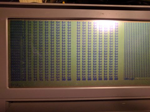
The format of MFM and RLL disks includes checksums after both the sector ID and sector data in order to confirm the data has been read successfully. For MFM drives, this was typically a 32-bit CRC, and the OMTI datasheet for the 5055 documents the polynomial used. For more information on CRCs, I found the wikipedia article very useful. RLL is storing data at a higher bitrate so controllers typically used a longer ECC code for the sector data, rather than a 32-bit CRC. The OMTI 5055B datasheet says it supports 16-bit and 32-bit CRCs (and lists the polynomials used), and also 48-bit and 56-bit ECC, the polynomials for which are listed as "proprietry". Reverse engineering the polynomial from data and ECC value is technically possible - but it's a a brute force process and isn't practical with current hardware; however, if you can write certain data, the process becomes a lot easier. Initially I'd thought about doing this, then looking at the /WRITE line and parsing the data being written to the disk, but whilst reading the int 13h functions, I came across function 0x0a - READ LONG SECTOR. The documentation for this says that it returns 516 bytes, rather than 512, with the last 4 bytes being the ECC value from the disk. That would be fine if we're looking at a 32-bit CRC, but less useful if it's a 56-bit ECC - we'd need 6 bytes of ECC. The only thing to do was to write a simple program that performs a hex dump of a sector, with a larger buffer to see what int 13h 0ah returns. This I did, and the result is very encouraging - it returns 518 bytes - so I'm hoping that this will allow me to reverse engineer the polynomial for the 56-bit ECC being used.
November 13th, 2017 - 18:43
Two sectors of 512 bytes is written per every SERVO GATE pulse
July 29th, 2018 - 13:37
Did you ever get this to work? I have one of these hard drives and I would love to access the data on it.
August 18th, 2018 - 17:52
It’s rather been put on the back burner, but I did get quite a way through. As with the MFM and RLL drives of the 80s, all the data encoding logic and configuration is on the controller, so getting data off a drive might be tricky, although not impossible. I’m hoping to be able to modify David Geswein’s MFM emulator to read the raw flux transitions from the drive, which would help