Sorry? I can’t hear you!
The original ZX Spectrum was typically connected to a portable audio cassette recorder to load and save programs. Later on, Sinclair released the Interface 1 with the Microdrive, a miniature tape interface that wasn't the most reliable (possibly a post on this at some point in the future). Several third party vendors released disk interfaces with varying degrees of popularity. For the most part though, tape was the the format software came on.
As time progressed, and every other system was already using disks (or so it seemed), Amstrad decided to try and breathe some new life into the Spectrum by releasing the +3, with its built in disk drive. Possibly too little too late, and probably not helped by their choice of format, the +3 was the last of the Spectrum line.
That bit of history over, on with my little project. As things stand after my last post, my +3 powers on and seems to work - that is until I try to load anything. Inserting a disk in the drive and typing "cat" (to get a catalogue of files on the disk), the drive LED lights up and the drive whirs for a few seconds, only to fail with a "Drive not ready" error. Ok - not totally unexpected - this system hadn't been touched in probably 20 years.
It only takes a few minutes to open up the system and remove the 3" drive (yes, it's an odd size). Unscrewing the logic board and peeking underneath reveals that the drive belt is almost unrecognisable: it has obviously perished, snapped, wrapped around the capstan on the motor, and turned into a nasty, sticky goo. Right - the drive clearly isn't going to work until that's cleaned up and replaced. Cleaning it up is easy enough - carefully peel and scrape the old belt and residue from the capstan, then clean it up with some isopropyl alcohol. Sourcing a replacement doesn't look too be too difficult - although it's an oddball size drive, Amstrad seemed very fond of it at the time and the same drive could be found in the +3, CPC, and PCW systems, not to mention the external drives for the above mentioned systems. As a result, there seem to be plenty of appropriate replacements on eBay and such for just a couple of quid each.
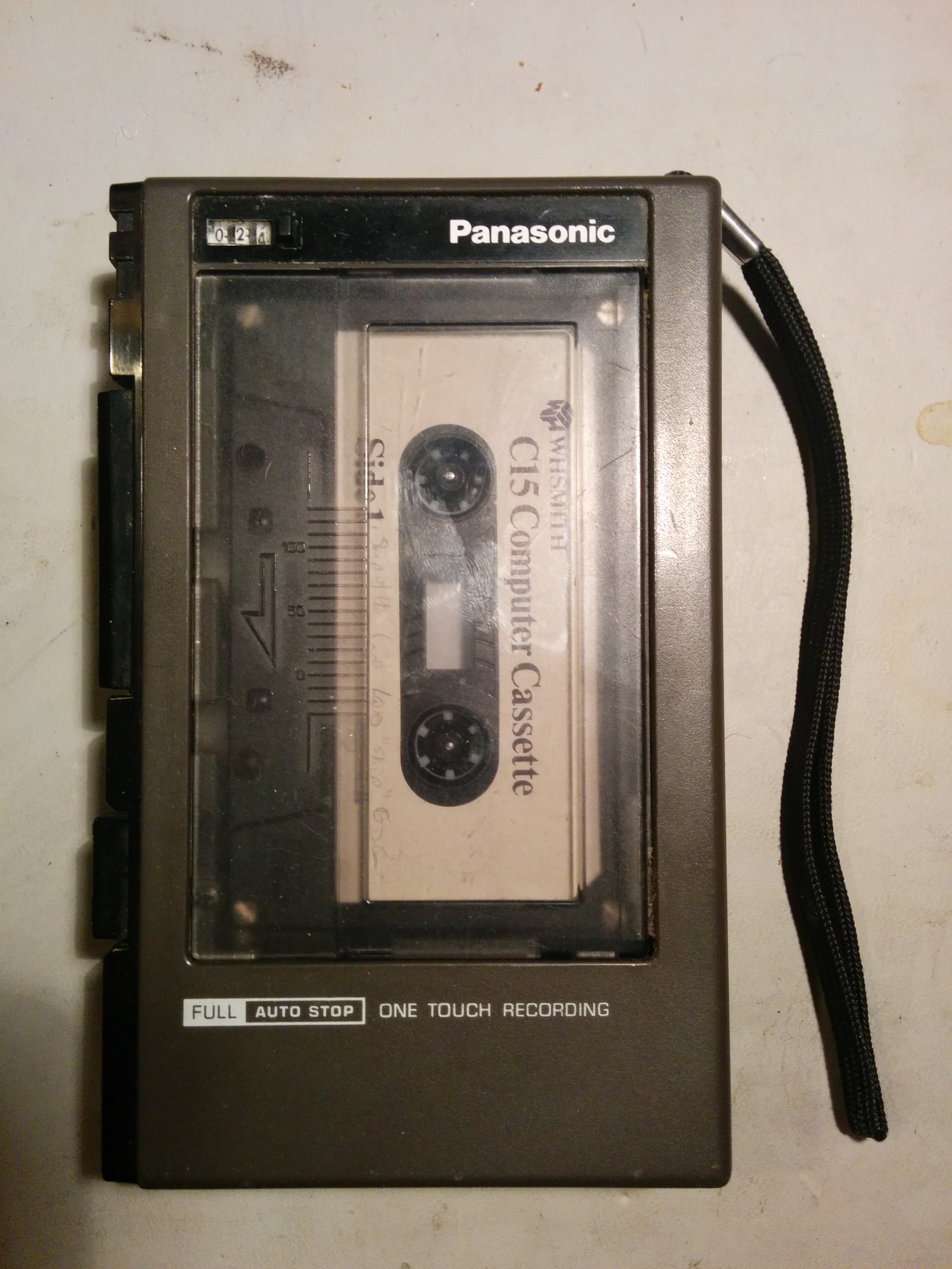
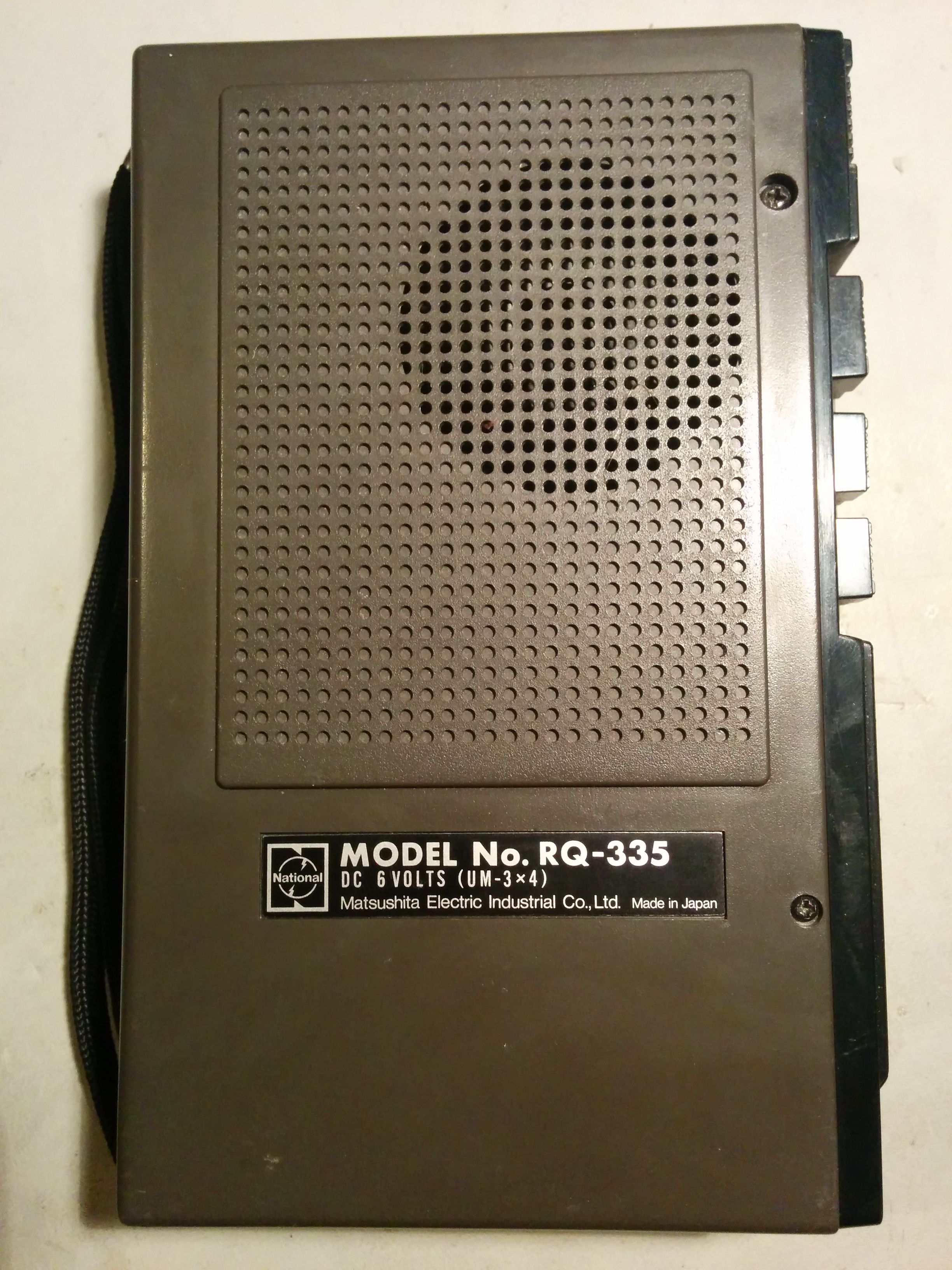
Clearly I'm not going to get much off my disks today, but that's OK - most of the software out there is on tape anyway, and I do have a little cassette recorder of the same vintage which still works a treat. Unfortunately, Amstrad figured everyone would want to use disks, so whilst the system does have a tape interface, a) it's a stereo jack with tip as output (mic) and ring as input (ear), and b) they didn't supply a breakout cable.
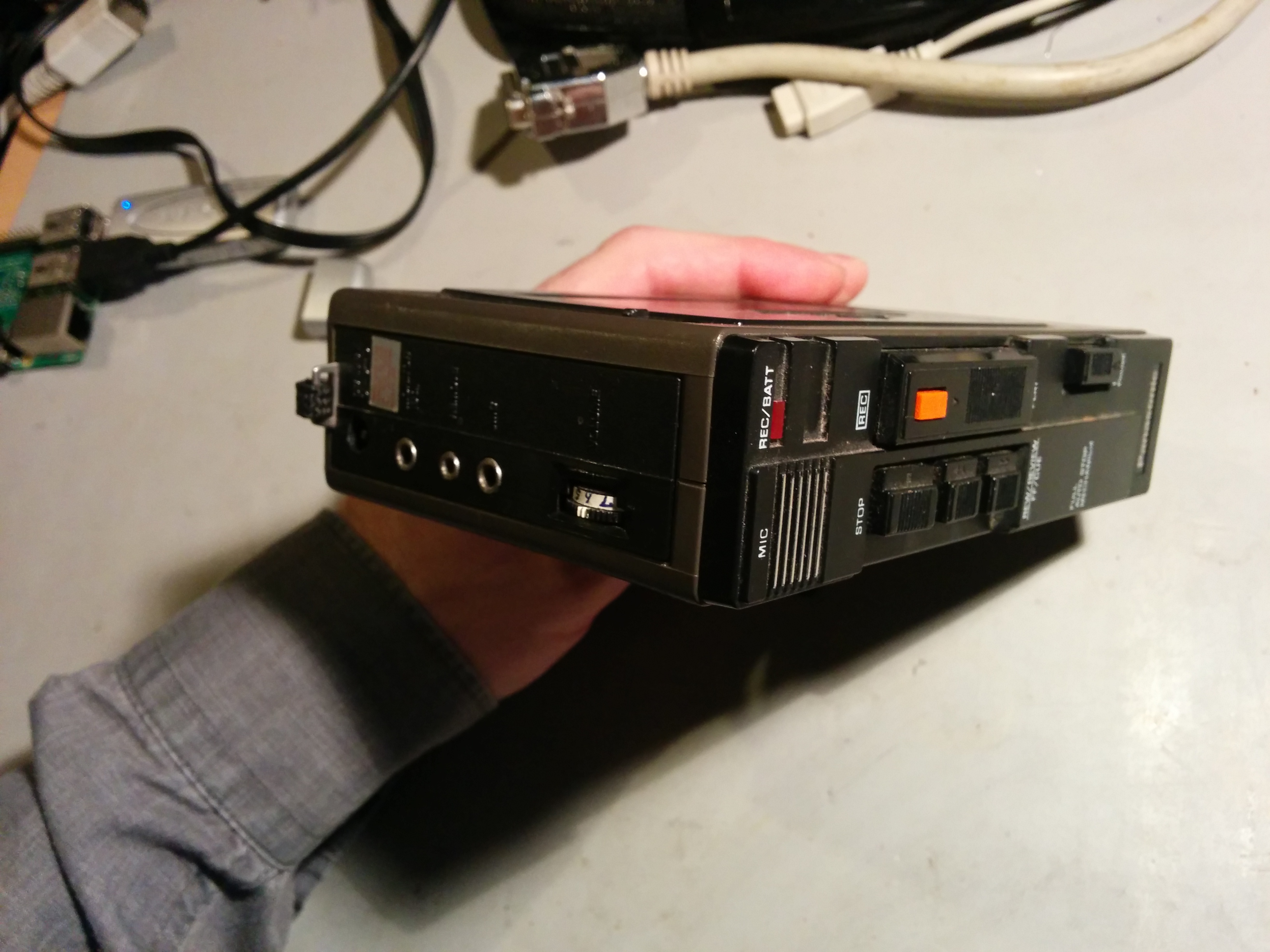
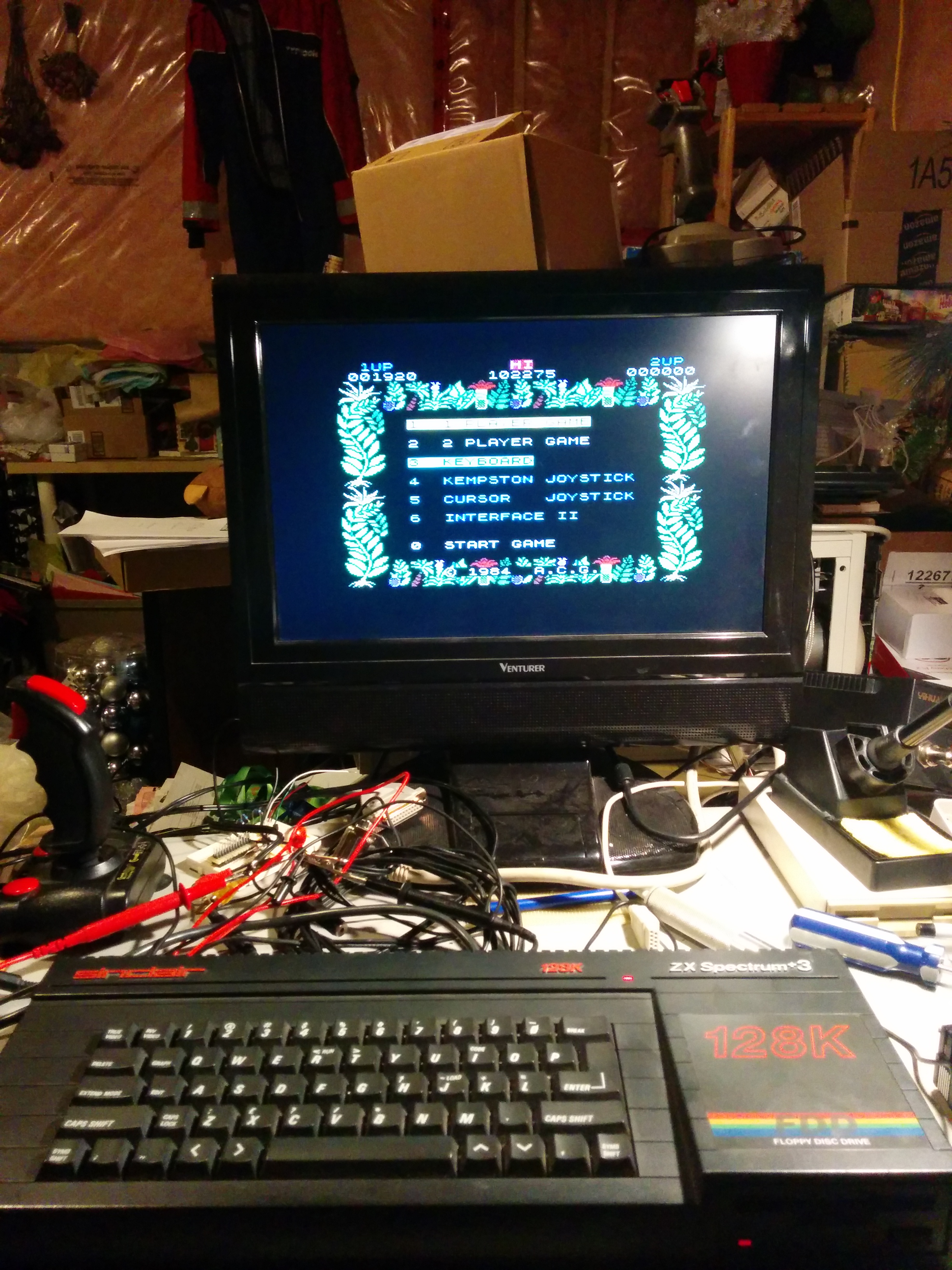
Fortunately, that's not a difficult thing to cobble together, and in fact, rummaging in my audio cables box reveals an appropriate cable I'd put together for something else. After confirming the pinout, I plugged one end of my cable into the Spectrum and the cassette player into the other, launched 48k BASIC, ran LOAD "", and pressed play. Nothing - no cyan/red flashing border, no cyan/red bars, definitely no yellow/blue bars. I fiddled with the volume on the cassette player, still nothing. Double-checked the pinout, nope - I was right the first time.
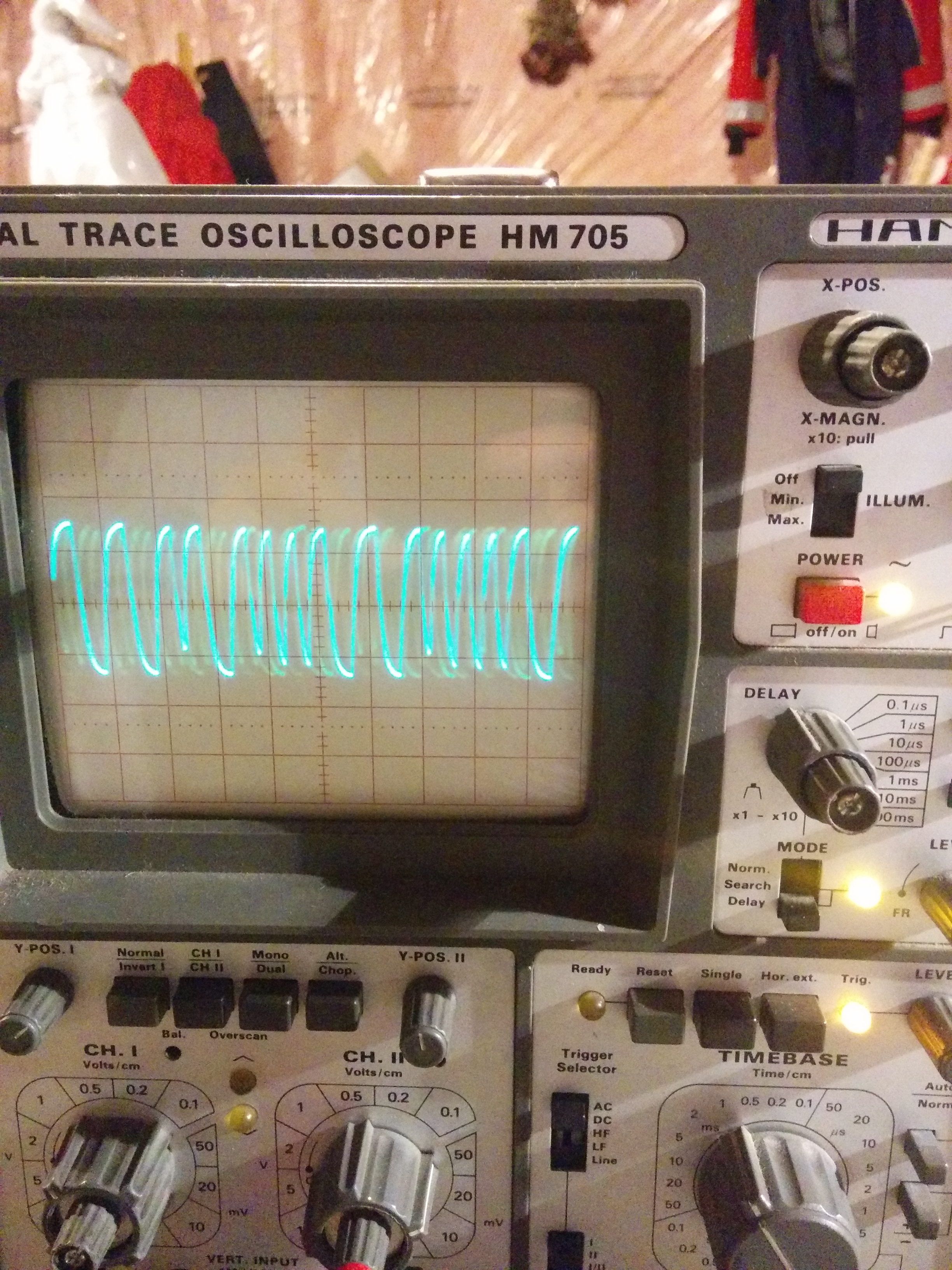
Time to break out some troubleshooting tools. If you've read my first post on this subject, you know I shipped my old Hameg scope along with the retrocomputers. Pulling this or and putting it across ring and sleeve shows a signal - and it also shows the little white mark on the volume control is in just about the right place, with the signal just before it clips at approx 3V peak-to-peak. Ok - so the problem must be in the +3. Let's open it up again.
Looking at the schematic, there's a filter capacitor in series with the tape input to remove any DC bias. It's easy to identify, and easy to get a test probe onto the legs, but powering things on and probing that gives nothing. Pulling the board out and doing a continuity check shows that tip and sleeve both make contact, but ring does not.
Seeing as the board was already out, it seemed a reasonable next step to desolder the socket. Once it was of the board, it was possible to see that the ring contact inside the socket was squashed to one side, which explains why it wasn't making contact. Repairing the socket probably isn't practical, so a replacement will have to be procured - another job for later. For now, I do have a spare panel mount socket and some test leads, so connecting that up temporarily and putting the lid back on allowed another test. This time...
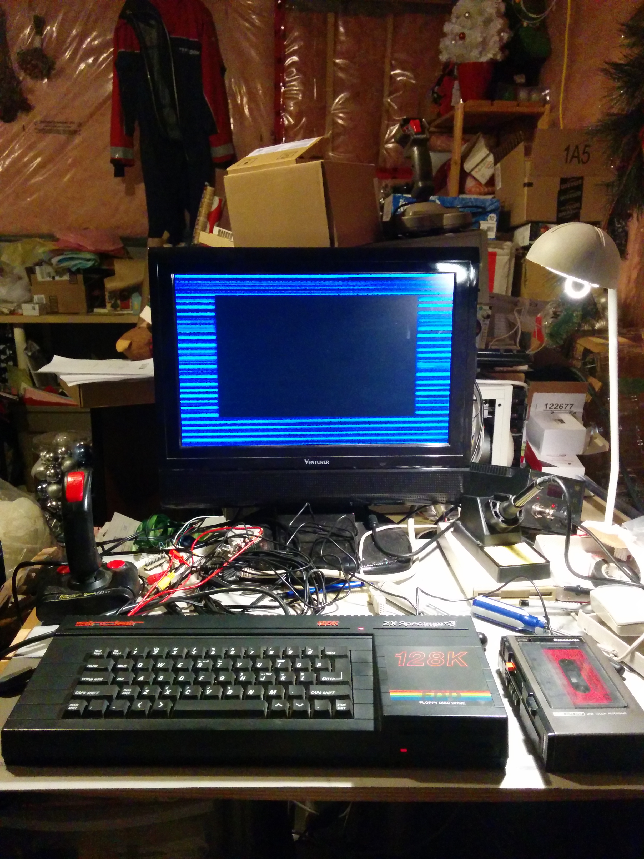
Success!
Leave a comment
You must be logged in to post a comment.