Adding composite video out to the +3
Now I have a working power supply for the Spectrum +3, I need some way to see what's being output. In its original configuration, video is output either a PAL RF signal on UHF channel 36 (UHF 36 was used a lot like VHF 3/4 in north america) or as RGB on the Peritel socket. The RGB signal doesn't help much here - whilst in the UK, TVs have a SCART socket with RGB inputs, in north america, TVs have YCbCr component inputs, so some circuitry to do conversion is required. That being said, the RF signal is generated from a composite signal - in earlier model Spectrums, it's just a matter of disconnecting the input to the modulator, disconnecting the output of the modulator from the socket, and connecting the input to the socket. Unfortunately, with the later model Spectrums, Amstrad mixed in the audio (as an FM signal), and that tends to upset TVs when you include it on the composite video input.
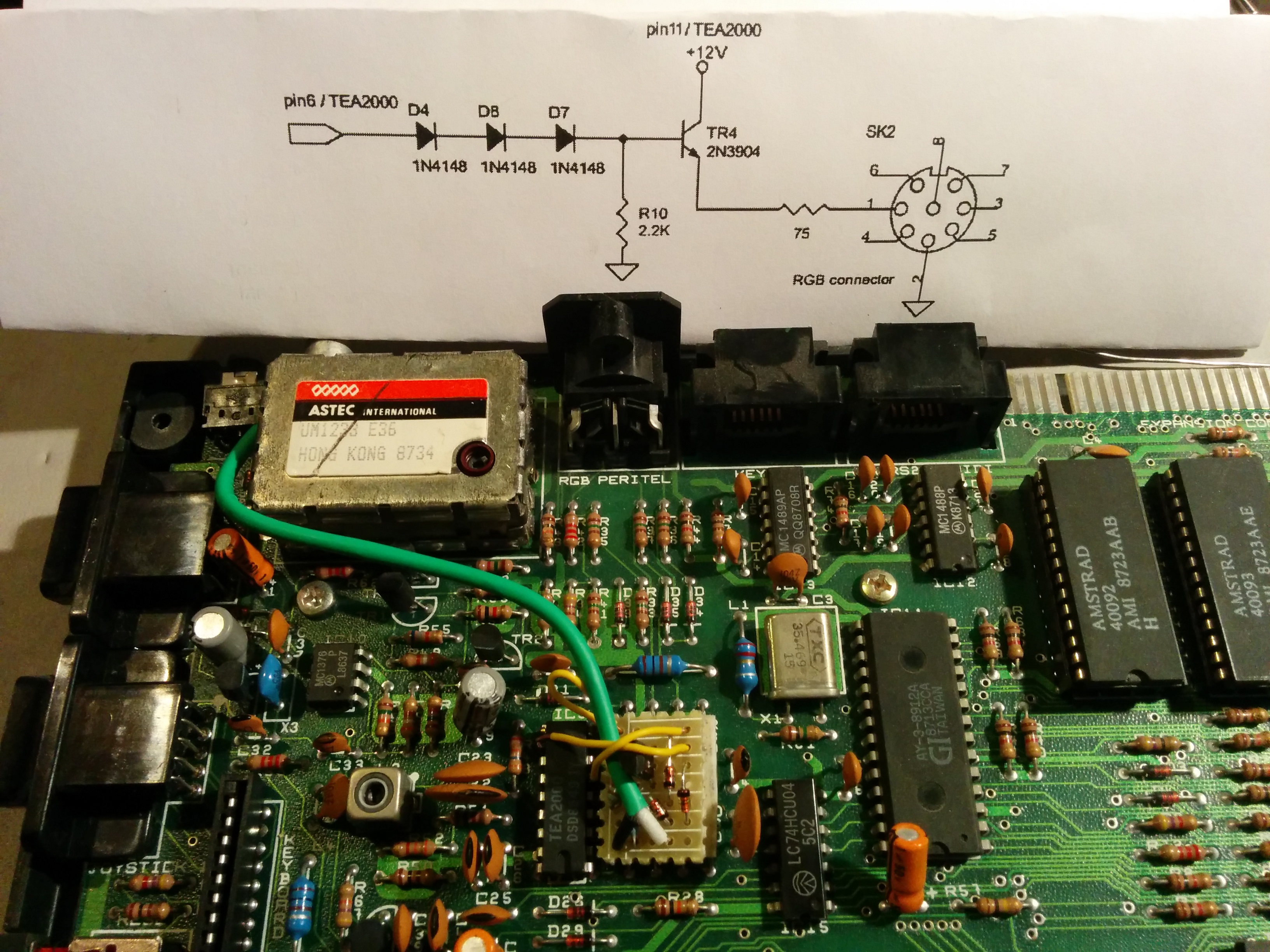
After a bit of research, and a review of the schematics, it's clear that internally, the ULA outputs a single bit for each of Red, Green, Blue, and Intensity. These are split, with one set of lines being combined and output as an analog RGB signal on the Peritel socket, and the other going to a Philips TEA2000 PAL/NTSC Colour Encoder. This in turn outputs a composite video signal, which is then combined with the FM-modulated audio signal, before being fed into the Astec UM1233 UHF modulator. The original Spectrum +2 took this composite signal, buffered it, and presented it on pin 1 of the Peritel socket; however, later systems replaced this composite output with a +12V pin, which isn't overly useful here. Luckily, I'm not the first person to run into this, and there's a well documented solution in this PDF from Ben Versteeg which basically implements the same buffer as existed in the original +2. As I don't need the RF output (and unless I import a PAL TV from Europe, I don't think I ever will), I can put the composite out on that connector.
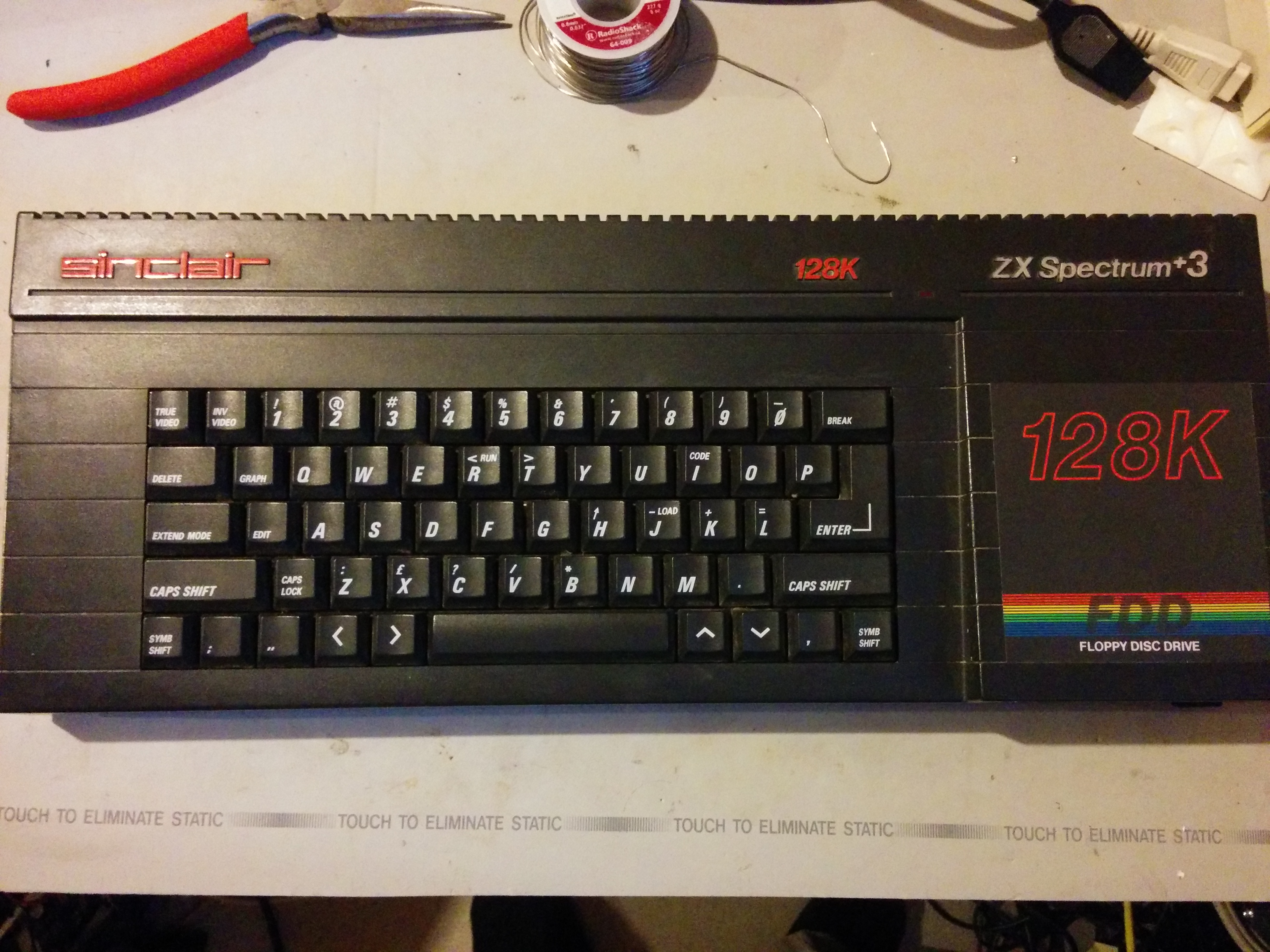
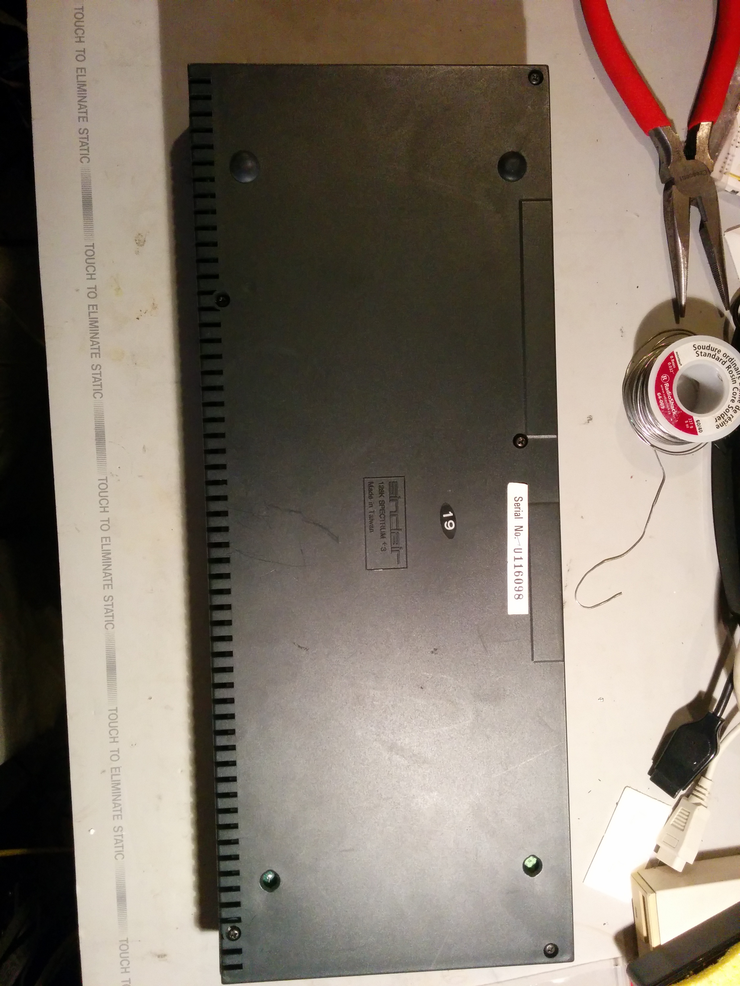
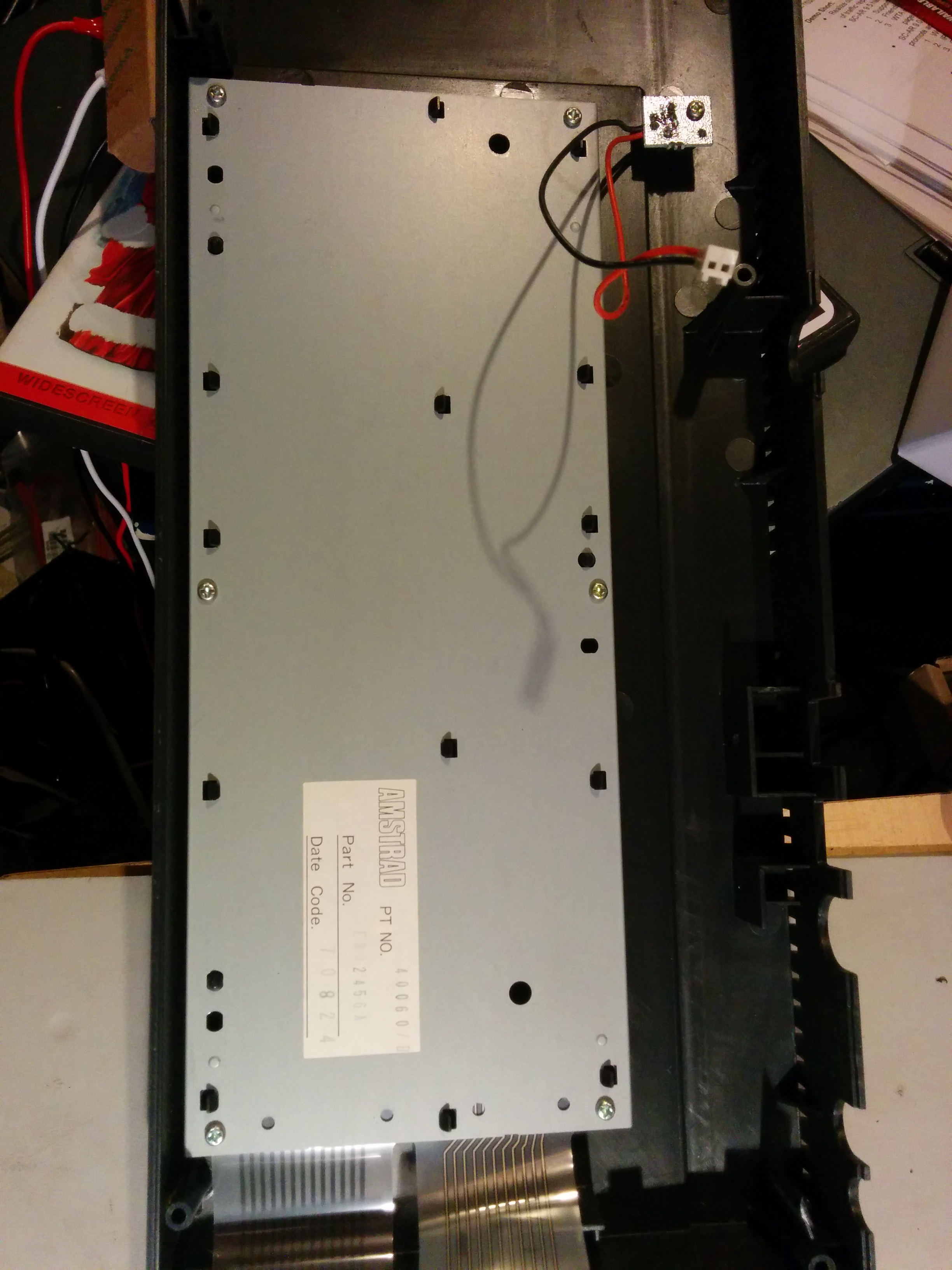
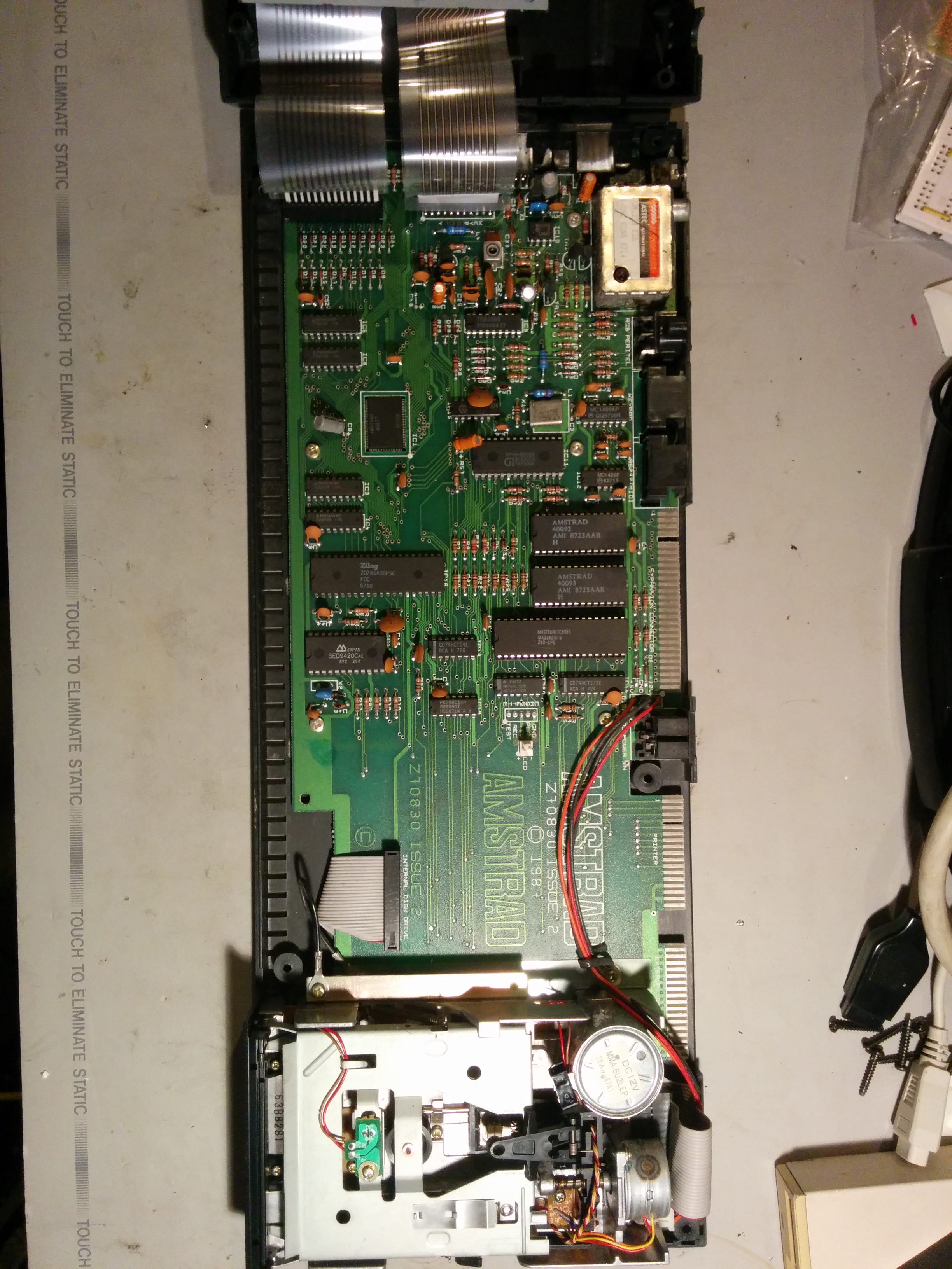
The first step in the process is to crack open the case, taking pictures for your viewing pleasure
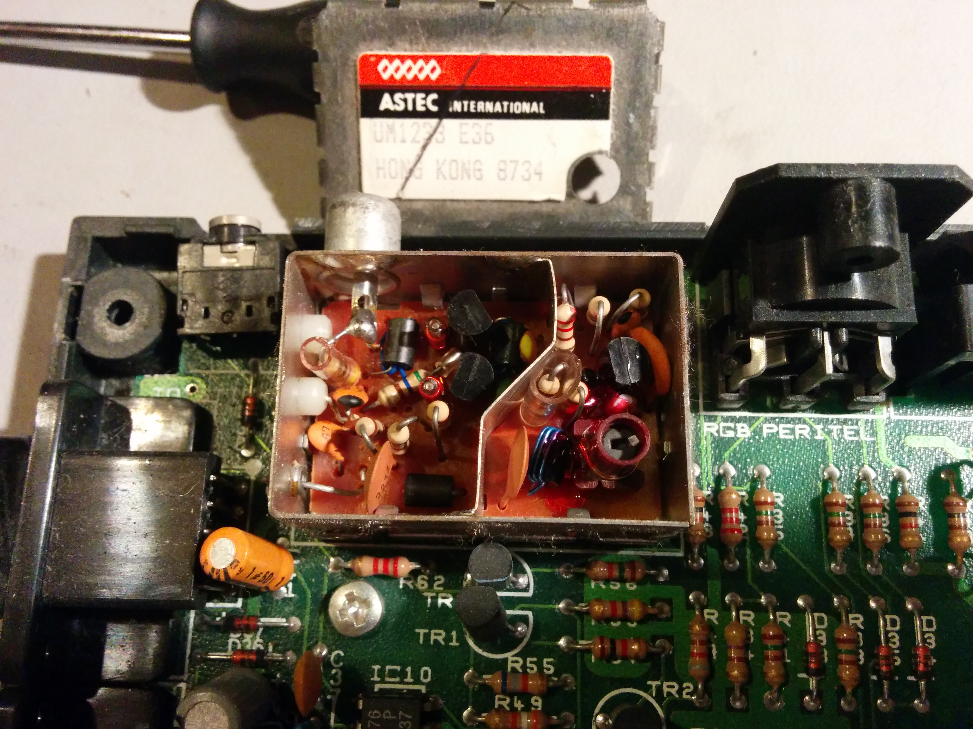
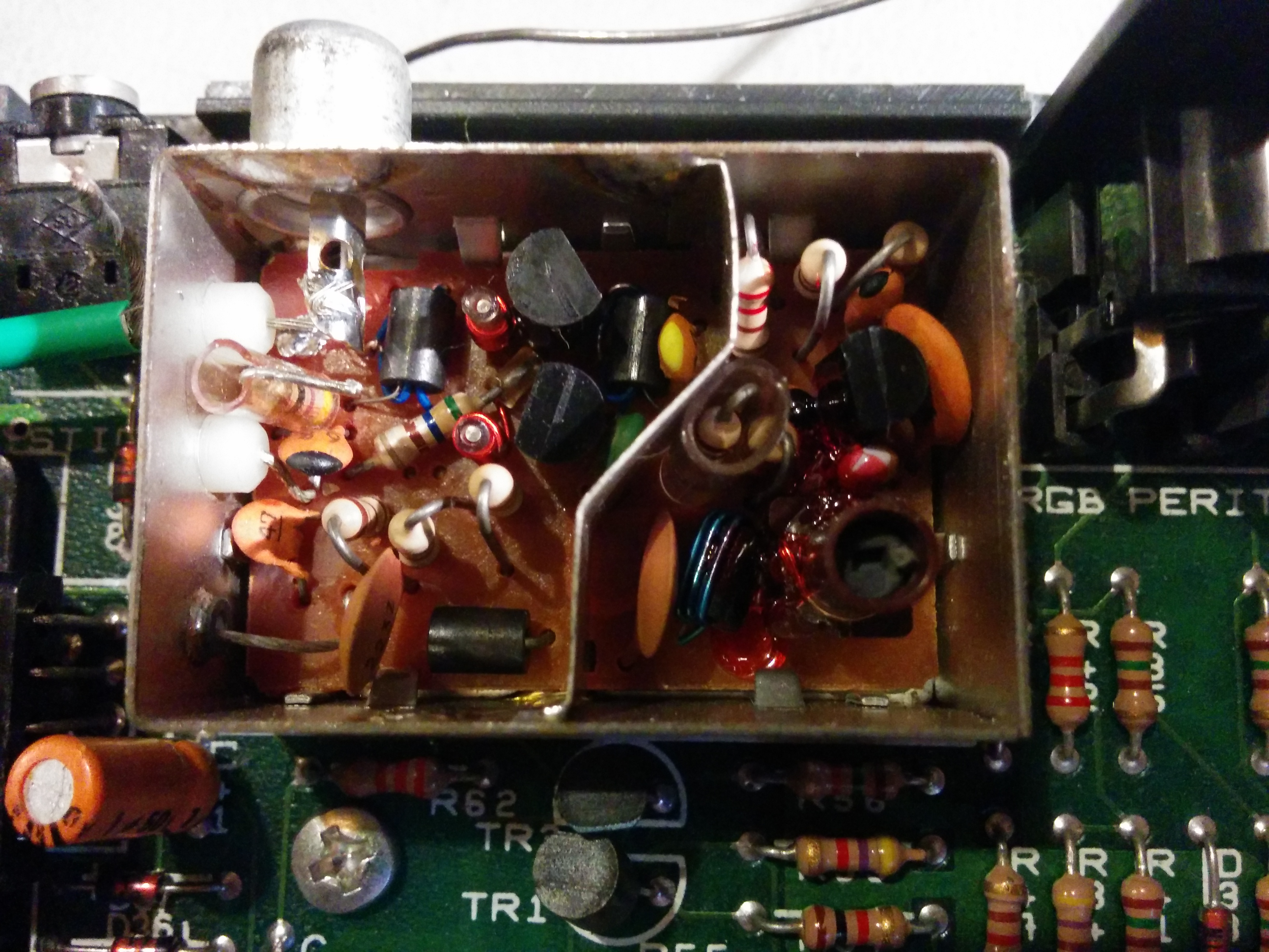
The next step is to pop the top of the RF modulator.
Then desolder the resistor connecting the modulator's output to the output connector. Rummaging in my box of bits yields some thin coax that should work to connect the output from the buffer circuit to the output connector. That's cut, stripped and soldered in place at one end.
There buffer itself is simple enough - it's just three diodes in series, feeding the base of an NPN transistor in a common collector configuration from the 12V rail. This was easy enough to assemble on a piece of protoboard, with three short leads soldered to the TEA2000 to pick up +12V, Composite Out, and Gnd.
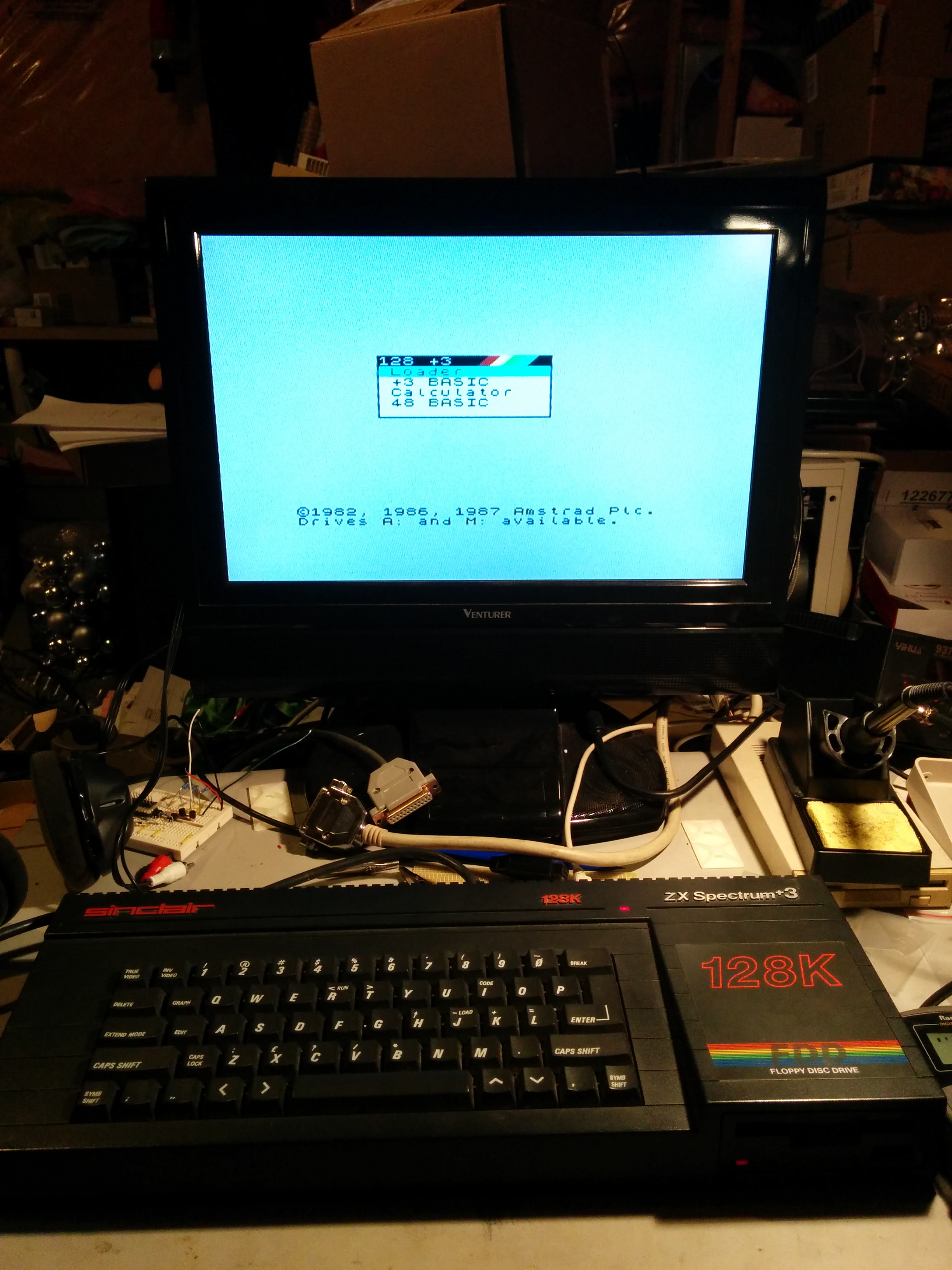
After reassembling everything, connecting the new composite out (the socket is conveniently labeled "TV", which is still accurate), and turning on the TV comes the moment of truth...

It works! A few cursory tests (10 PRINT "Hello world "; 20 GOTO 10) and all looks good.
Next up - loading software
Leave a comment
You must be logged in to post a comment.