Replacing the ZX Spectrum +3 PSU
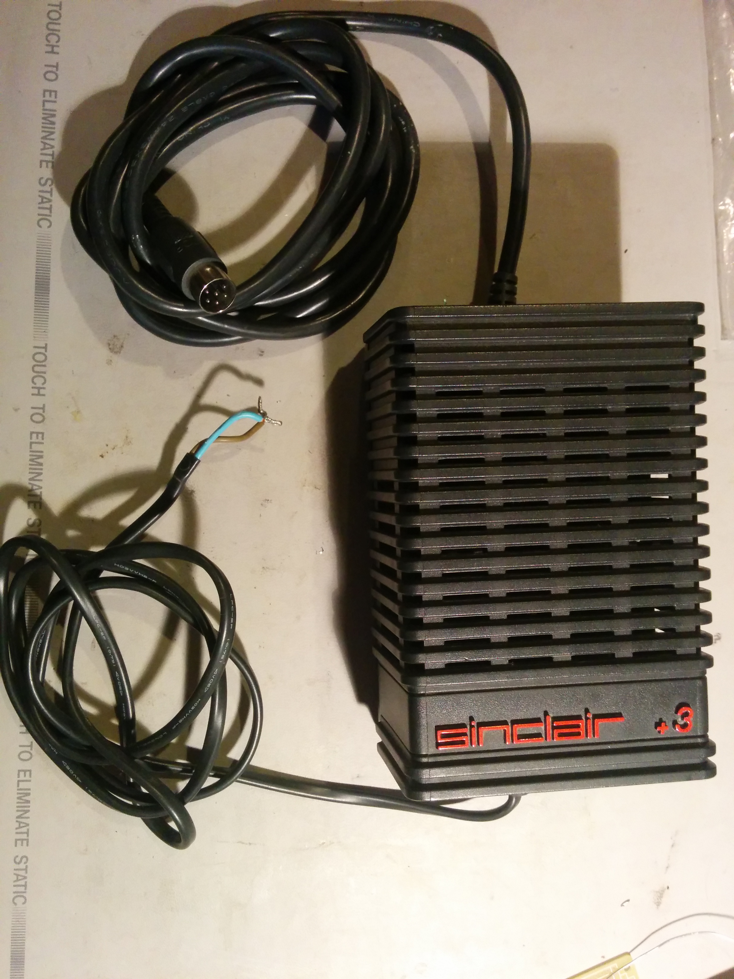
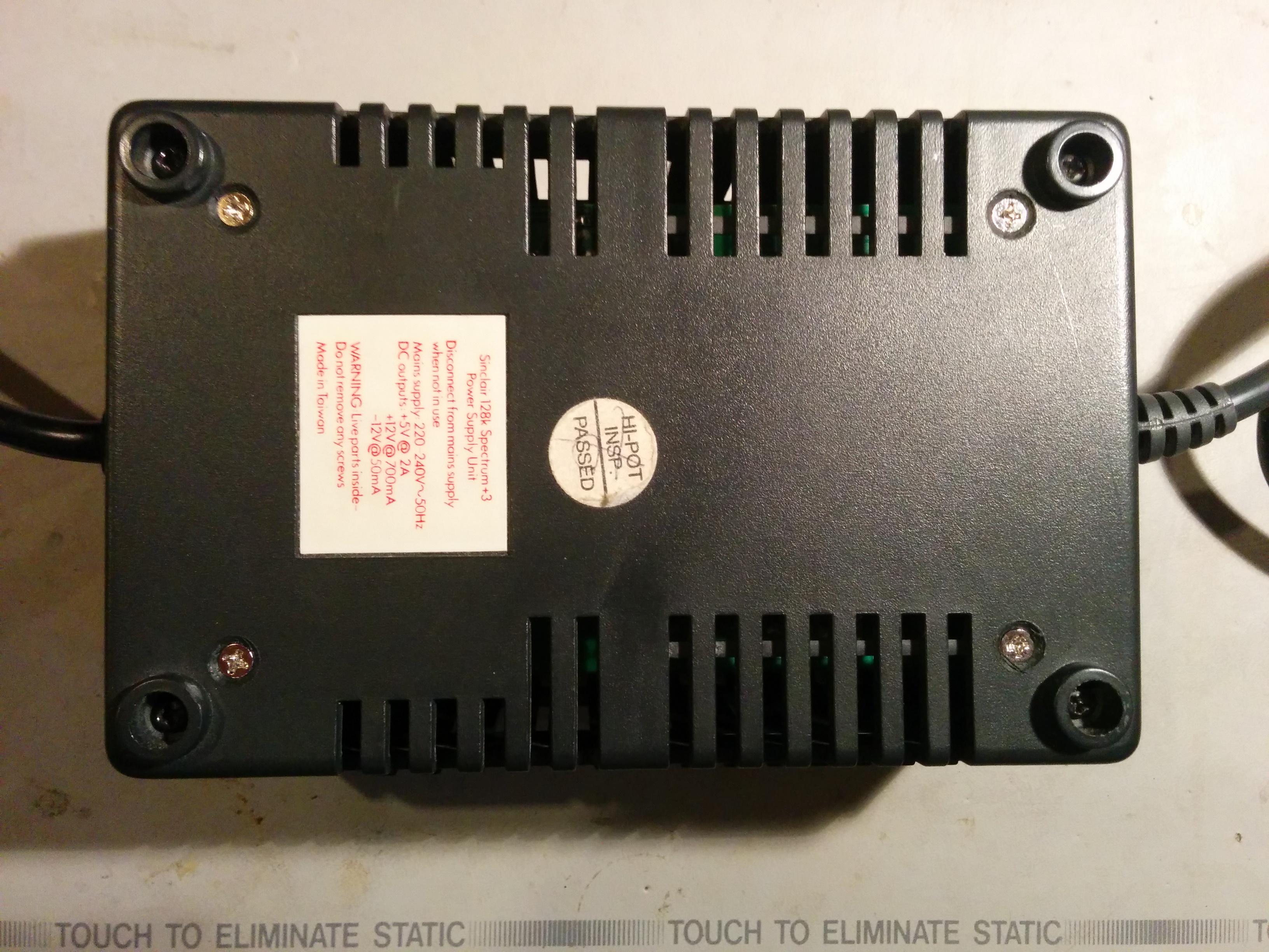
Seeing as the A1200 PSU replacement went so well, it was time to have a go at the ZX Spectrum +3. Much like the A1200, this also requires +5, +12, and -12V rails, with a similar sized casing (slightly wider and shorter). The original PSU was linear with a big, heavy, transformer - not ideal when you're trying to keep weight down for shipping. As a result, I'd already opened up the case and removed the existing supply before shipping the system. What I had in front of me was an empty shell.
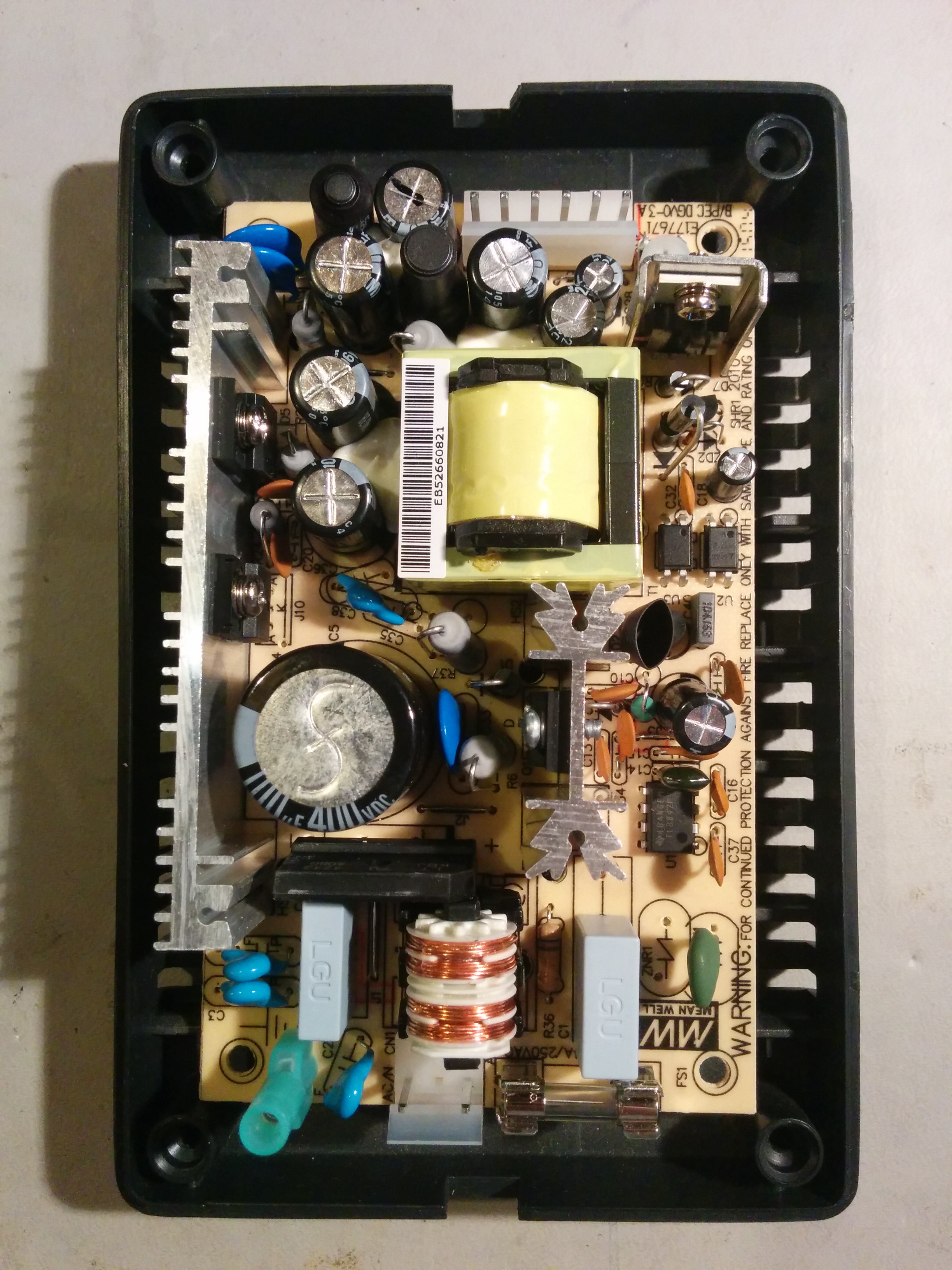
Unlike the A1200 PSU case, the +3 case splits into a short base section and a larger top cover. This means we shouldn't have the same trouble with internal posts getting in the way - or if we do, we don't need such long standoffs. Putting the Meanwell PT-45B board just inside the base is a perfect fit - it could've been designed for it.

As I did for the Amiga PSU, the first step is to make standoffs - in this case ii's easier - just take two if the 1/4" diameter by 1" long spacers and chop them in half with a Dremmel.
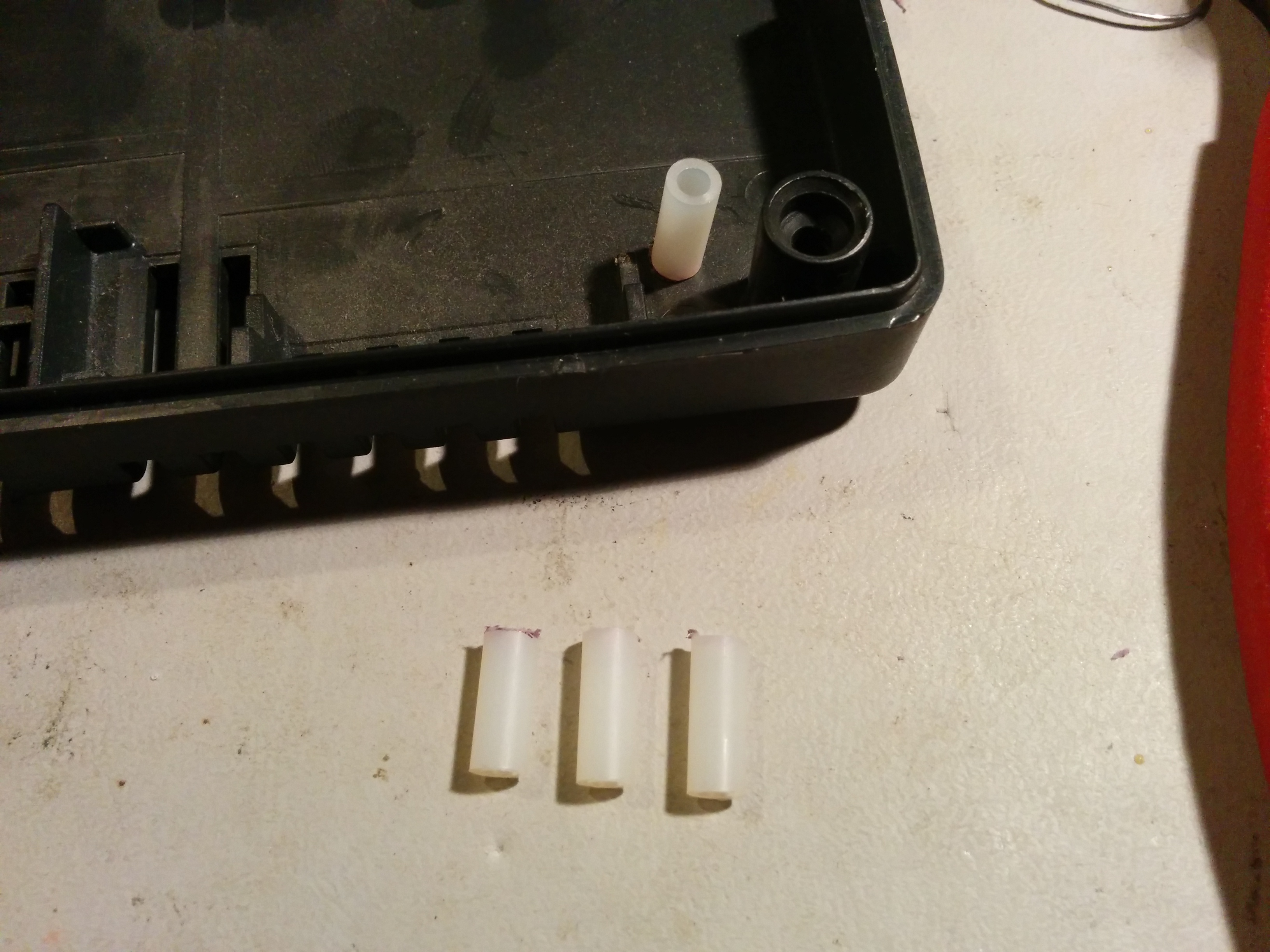
Transfer the position of the mounting holes onto the base and drill+countersink the corresponding holes. Attach the standoffs to the case using regular countersunk hard disk screws.

Screw the new board into place and do a quick test fit of the lid and all looks well.
Carefully move the strain relief on the output cable another inch along to give some more wire to work with inside the PSU. Ringing out the power connector shows that rather pleasingly, red is +5, yellow is +12, black is Gnd, and blue is-12. The input cable is only two core, as the original supply want earthed, whereas the new board is, so rather than reuse the old cable, I took an existing PC power cord (of which I have many) and chopped the C13 connector off, feed it through a rubber grommet that will hold it in place, and stripped a couple of inches of outer insulation of the end. Then it's just a matter of attaching connectors to the end.
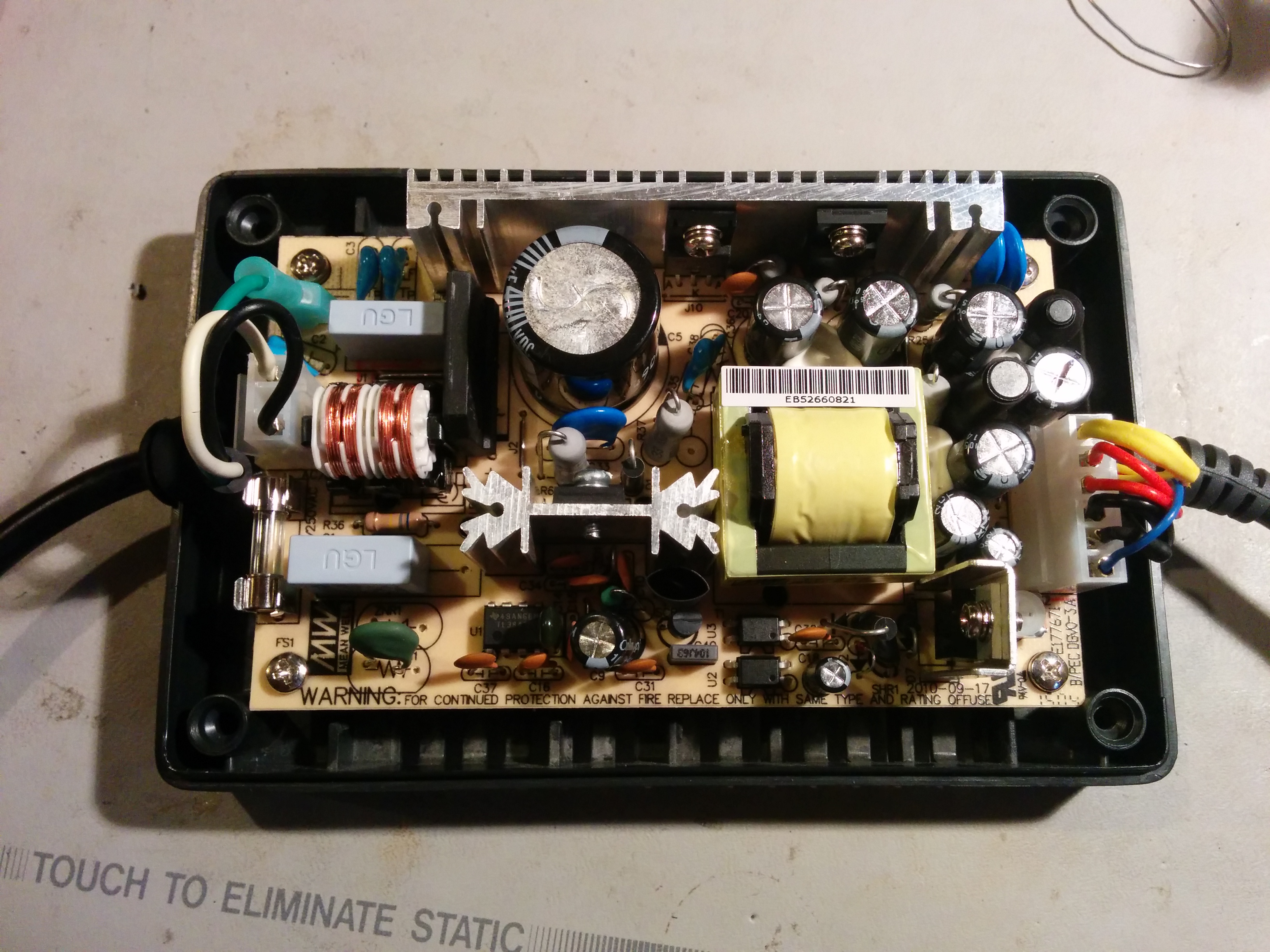
With the connectors installed, and the PSU board mounted inside the case, all that remains is to plug everything in and close up the case

Plugging it into the Spectrum gives a red LED and a brief whir of the drive motor, which is promising - that's the normal power on sequence. However, without a monitor that can take the RGB output, or a TV that can accept a PAL RF signal, that's as far as this takes us. Next step - replacing the RF output with composite video!
June 21st, 2016 - 14:17
How about different potentials of this PSU and TV Scart?
Old PSU was connected to 230V by 2 wires only. This new is connected by 3 wires. Input is coupled by cap N to PE and L to PE. And what is important – output is coupled by cap Ground (com) to PE by cap too! It can be dangerous when potential of PSU will be different than TV…
December 8th, 2019 - 16:19
Somewhat of a late reply, but I came across this post today as I replaced the insides of the +3 PSU with a Meanwell RPT-60B.
Regarding different potentials, there is no issue provided safety ground is connected. Even if it is not, because the 0V is only capacitively coupled, no large amount of current can flow. The most that will happen is you will get annoying interference on the picture