Replacing the A1200 PSU
So January has rolled around and all my stuff from the UK is still sitting in the basement untouched. January is Retrochallenge time - I had intended on working on my 48k Spectrums, but I don't think that's going to happen for a while yet. However - getting my A1200 and +³ up and running seems like a good start.
My A1200 was purchased, second-hand, for a friend at highschool as a replacement for my much loved A500, which by the mid-90s was getting a little long in the tooth. The A1200 represented quite the upgrade, going from a 68000 to a 68EC020 and it had a massive 60MB hard disk (compared to the 20MB I had in my A590). If memory serves, it set me back £60 - which without a job is rather a lot. It was my main machine for a while, before I got my first IBM PC (we had a family PC for quite some time), but that's a story for another post.
Anyway, back to the task at hand - being a UK system, it has a 240V PSU and PAL video. The latter shouldn't be a challenge, as most modern LCDs should be able to accept a composite PAL signal, however the PSU isn't quite so straightforward. The A1200 requires +5, +12, and -12V lines, which is fairly standard, with the 5V line carrying the most current. I had a poke around on the usual sources and found what looked to be a suitable replacement module manufactured by Meanwell - the PT-45B. This was available from mouser, so I ordered two (you'll see why in the next post).
The first step was to open up the existing brick and pull out the original PCB. A quick snip of the existing wires from the board (would've cost commodore a few cents to socket them) and it's out. Sitting the side by side looks like the Meanwell board should be a good fit.
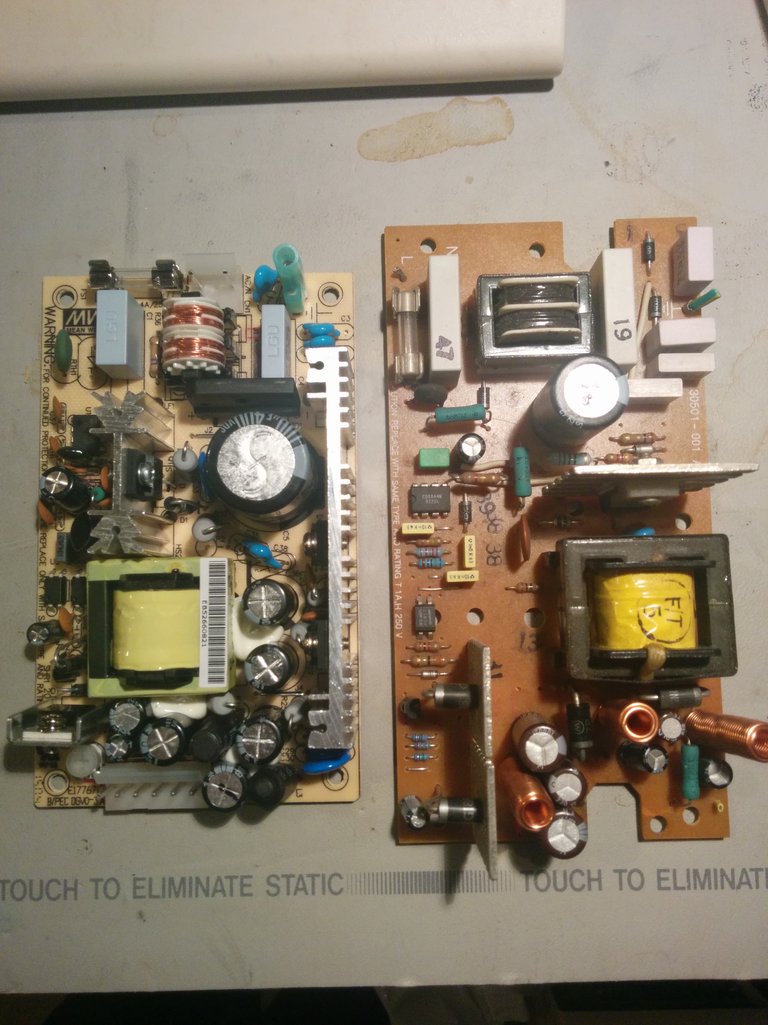
Meanwell PT-45B on the left, original A1200 board on the right
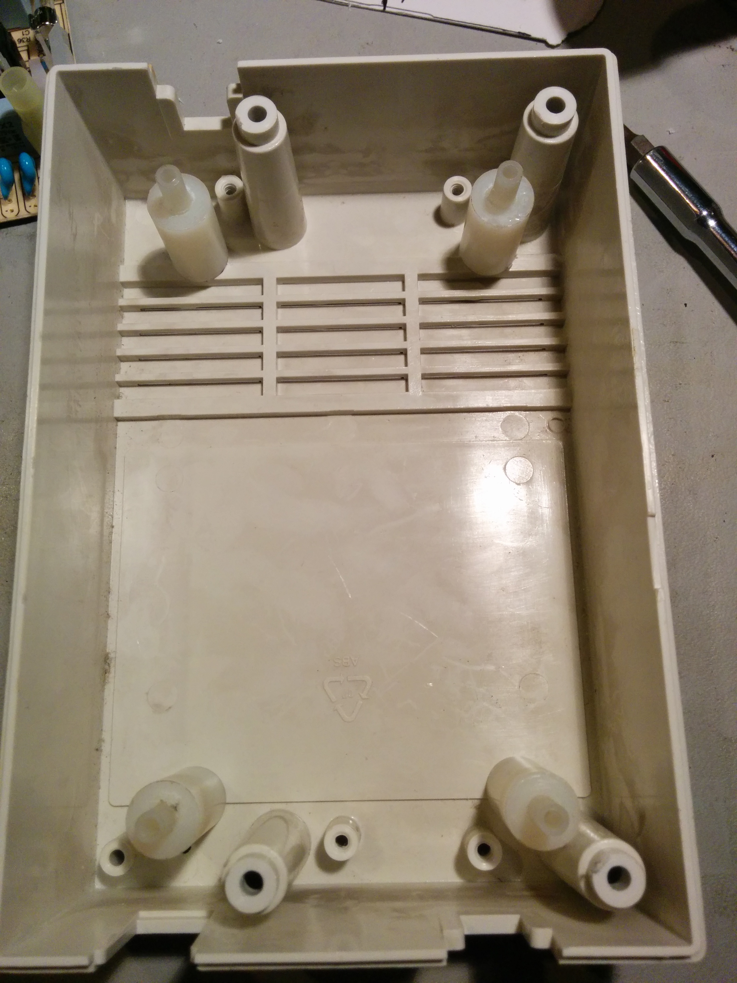
Next step was to lookup a pinout and ring out the wiring for the existing cable. Having done that, the next step is to mount the new PCB in the existing housing. Due to the design of the posts that secure the two halves together, the new board will fit comfortably in the top half, but not in the bottom. I don't want to mount it upside down, so I still get airflow properly through the vents. The solution is to put it on standoffs so it sits halfway up, essentially level with the top edge of the bottom half. This was easily accomplished with some nylon spacers picked up from Lowes - four 5/8x1" long with a 1/4" inner diameter; and four 1/4x1" long with a 1/8" inner diameter. The thinner ones will take a regular PC motherboard/HDD screw, and fit tightly inside the fatter spacers. The addition of some super glue and we have standoffs.

I made a cardboard template with the screwholes for the new PCB, allowing me to squeeze it between the lower case posts and transfer the marks onto the base. Once that was done, I placed the posts over the marks and checked it against the new board - everything lines up, but two of the posts are half over a ridge in the base, so they needed trimming to fit.

Once they sat flush, I drilled holes in the base and countersunk them, so the standoffs could be firmly attached.
With the standoffs now in place, the board could be fitted and screwed in place.

Next step - carefully slide the existing strain relief a little further down so there's a bit more wire to work with inside, then attach appropriate connectors to mate with the PSU board.
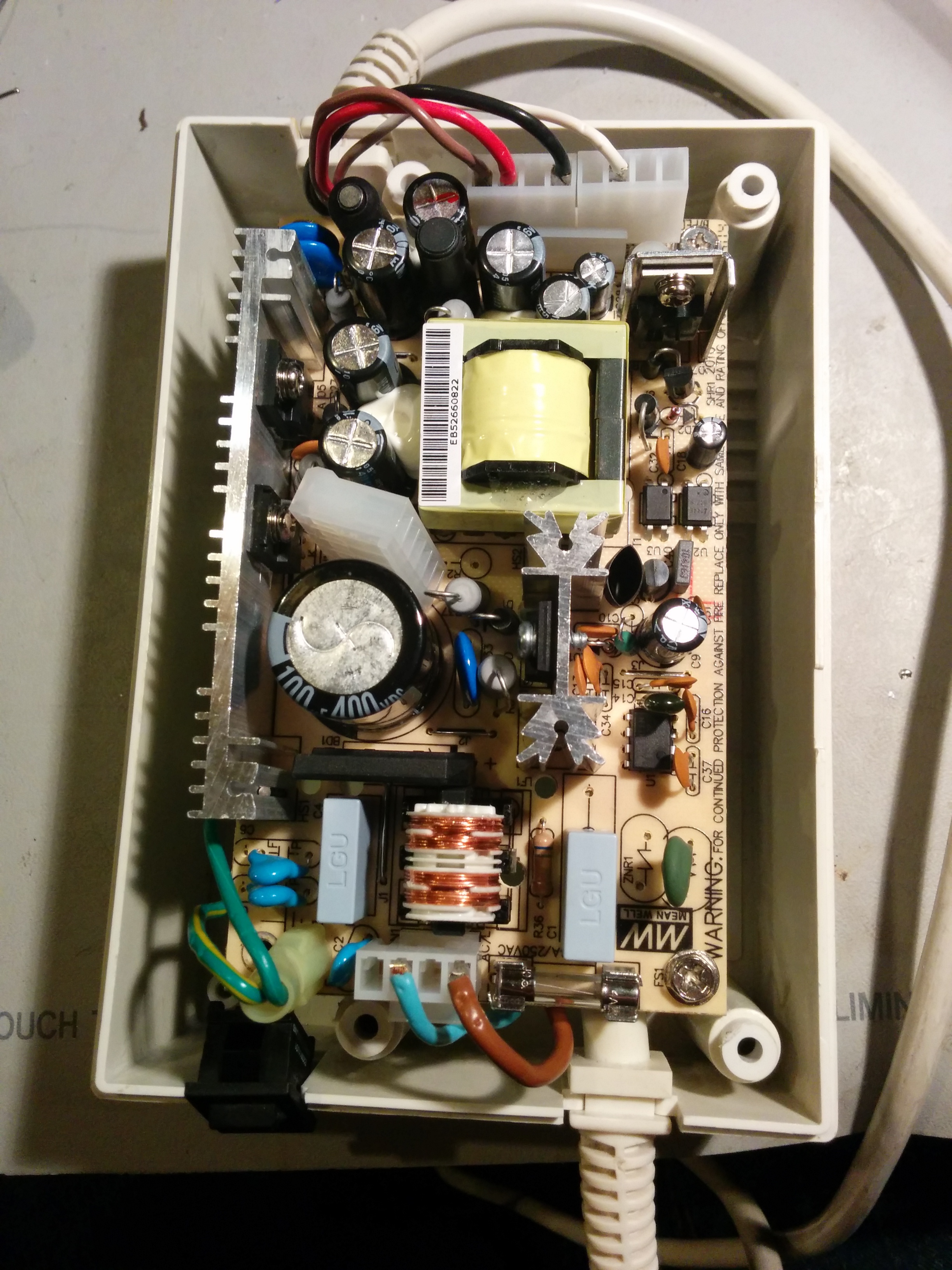
Screw it all back together and it looks just like it did originally. Now we just need to plug it in...
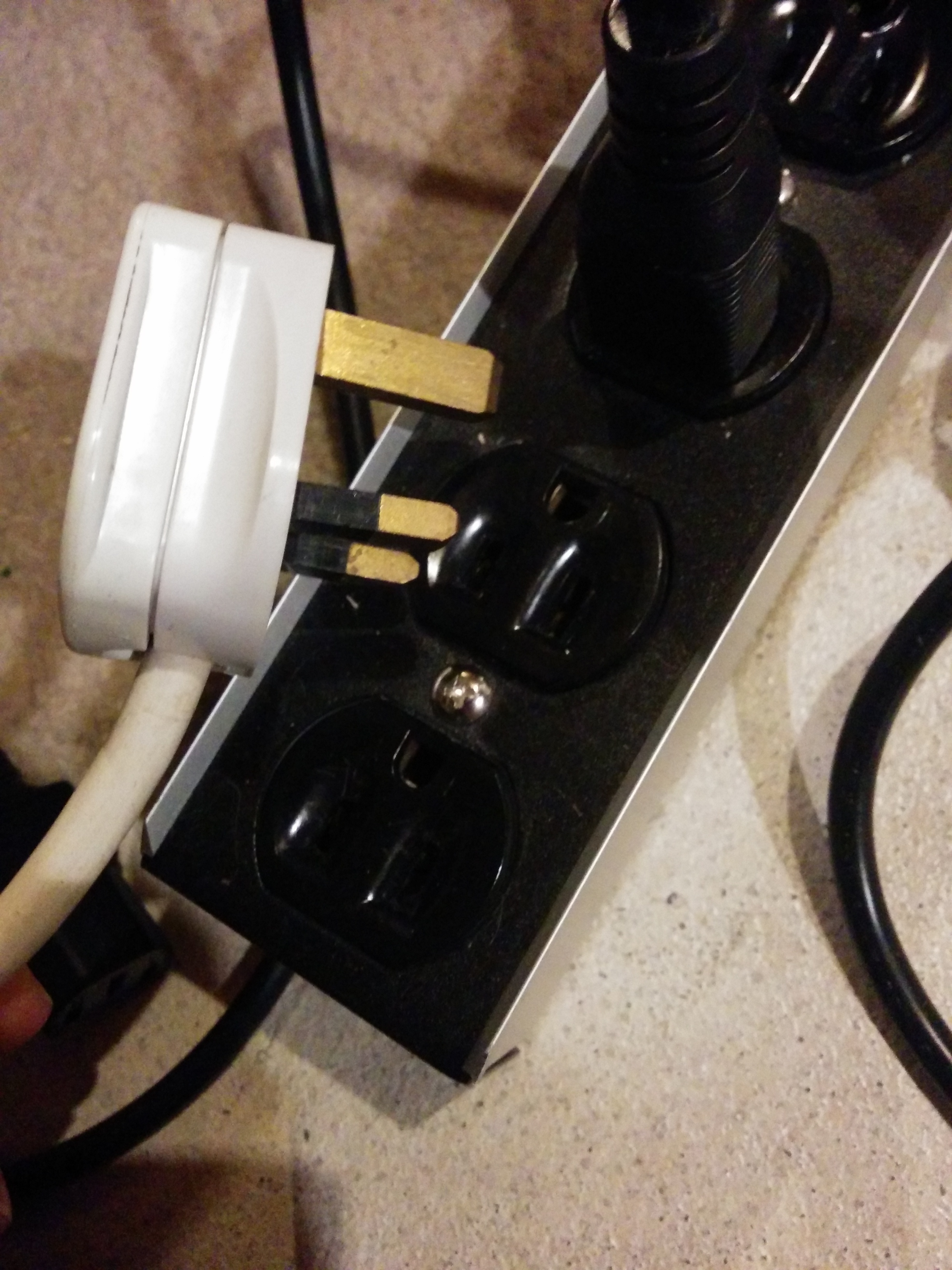
Well that's not going to fit...
Maybe swap that plug first 🙂
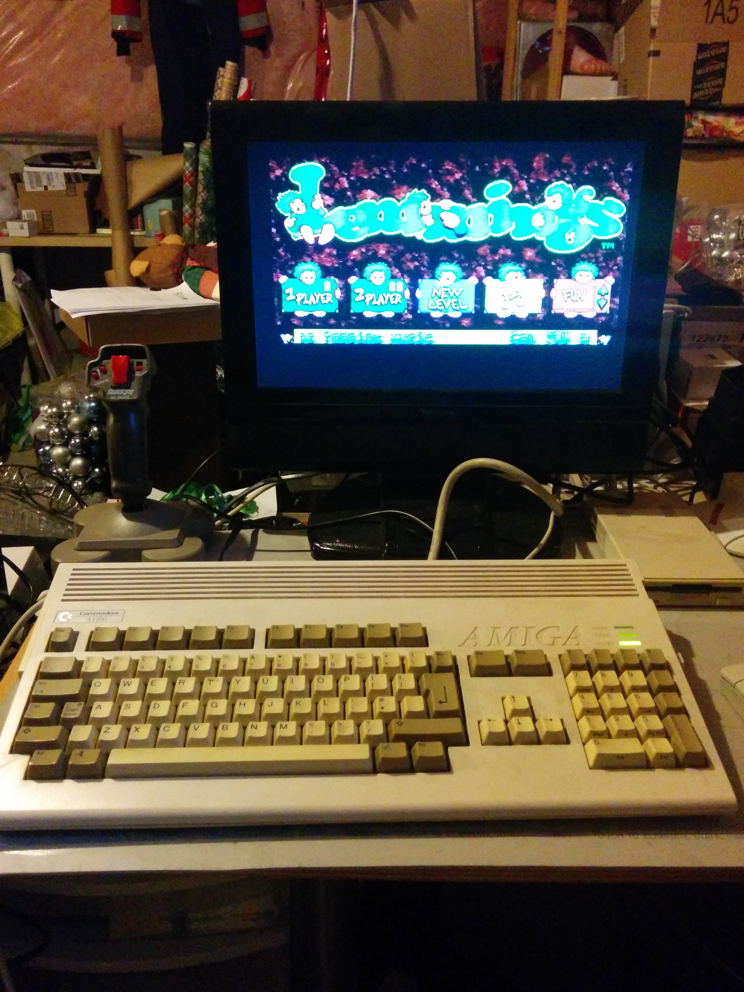
Plug it into the little LCD I have and turn on the power...

I haven't seen that desktop in 10 years - just how I left it. A quick rummage through the box of disks, and I can leave you with this parting photo:
Leave a comment
You must be logged in to post a comment.