In which the author comes to grips with the SMPS
Power supplies are probably something we all take for granted. Pretty much everyone knows that if you plug an electronic device into the power outlet on the wall, there's a thing called a power supply that somehow converts the mains voltage to something lower (and safer). I suspect most people reading this post know at least a little more than that, maybe something about transformers. Perhaps like me, you're familiar with unregulated DC supplies (step down the AC voltage with a transformer, rectify it with some diodes, then smooth it with some big capacitors) and linear regulators (take an unregulated DC voltage and essentially dump the excess above the preset output voltage as heat), with a vague awareness that Switch Mode Power Supplies are far more common these days, and much more efficient.
In my case, I've done plenty of simple linear regulators. They're dead easy to build (something like a 7805 basically just needs some decoupling capacitors and you're good), but not very efficient if they have to drop more than a couple of volts, especially at higher currents - that translates to a lot of heat. Switch mode power supplies are a lot more efficient, and are what you find in pretty much everything these days. I knew vaguely how they worked - you rectify your line input, filter that with a big capacitor, then use an appropriate MOSFET transistor to switch that on and off through the primary winding of a transformer, which induces a current on the secondary, which you then rectify and filter which becomes your output, with a feedback circuit that's connected to the controller on the primary side via an opto-isolator to keep the output voltage regulated. This wouldn't be possible without a controller, and these are readily available as a single IC and a handful of components to support it.
Still with me? Ok - I'm not going to try and make this an explanation of exactly how SMPSs work - there's plenty of good tutorials on that out there. This is going to be more about what I learned about switchers over the past week, and why. As I detailed in my last post, my V86P would originally have come with a PSU that provided 8.5V to power the laptop, fed through a small circuit to provide the battery charge line, and another line that controls the charging behaviour. Unfortunately for me, at some point in the past my laptop was parted from its PSU - I don't know if it died, was broken, lost, or any other malady that separated it from the laptop. Following my last post - I know the pinout of the PSU, I even know what the output circuit and charger look like, but that doesn't help a great deal without an 8.5V supply. Up to this point, I've been using an old HP bench supply, capable of supplying 8.5V at 1.2A; but a bench supply isn't overly practical, and 1.2A isn't up to the 4A spec of the original PSU (despite the laptop only claiming to require 8.5V @1A). I know from another V86P user with a dead PSU that the PlayStation 2 PSU is a sufficiently beefy 8.5V supply - they're readily available and inexpensive. But where's the fun in that?
On the top shelf of my desk, above the 1983-vintage tape deck and amplifier, is a generic third-party laptop PSU - the kind where the output voltage is determined by the connector you plug into the end of the cable. I used this for a couple of years with my old HP laptop after its original PSU died, until this one too decided to pack up with the familiar "tick-tick-tick" of an unhappy switcher. The issue with the original HP supply was damage to the output cable where it exited the strain relief causing the PSU output to be shorted. I'd fixed this by opening it up, chopping a few inches off the cable, and soldering it back in. When I'd tried this with the generic unit, it was still unhappy - hence why it ended up sat on a shelf for several years waiting to be looked at (and for me to understand how it worked). Now, between then and now, I've started watching a number of youtube channels which include a good chunk of electronics repair (folk like bigclive, Dave Jones at the EEVblog, thesignalpath, bandersentv, shango066, etc).and know that these things are typically repairable, once you know where to look.
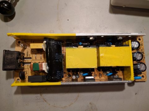
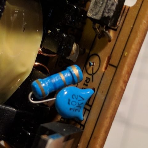
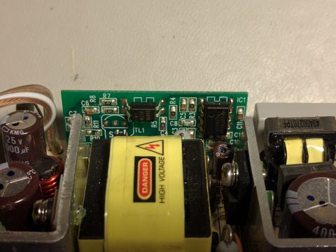
I started in a similar way to the V86P PSU, doing some simple reverse engineering from the PCB (it really is quite simple with a single-sided board), then looking for datasheets for the ICs being used. From there, I was able to doodle the schematic and start figuring out how things work. During this process, I found a resistor that had failed - but when I looked what it was doing, it was just part of a filter across one of the two rectifier diodes. It's unlikely this would cause the unit to fail in the way it had. Reading the datasheet for the controller IC was very helpful - there's a reference schematic, which I was able to compare against the one I'd reverse engineered from the PSU. That helped with identifying what some of the parts were doing. On the primary side, the input goes through a fuse and a thermistor (which provides some protection for the rectifier diodes at initial power on as the capacitor charges). Then there's an X capacitor across live and neutral and a common-mode choke in order to provide some filtering, before passing through a bridge rectifier to get a DC voltage, which is then stored in the bulk electrolytic capacitor. There's a high value resistor to provide a tiny startup current for the controller to allow it to start up, and a high power MOSFET that switches the high voltage DC through the primary winding of the transformer. In this case of this PSU, there are two MOSFETs and two output transformers which are operated in parallel. Both transformers have a third auxiliary winding, one of which isn't used, and the other goes through a rectifier diode and is then used to power the controller.
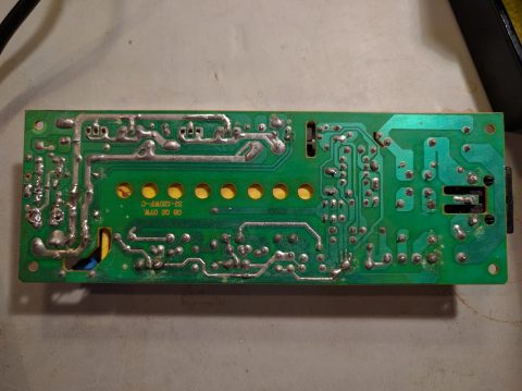
The secondary winding of each transformer goes through a high-speed recifier diode with an RC filter across it, the output of each is then wired in parallel, and then filtered with a capacitor, inductor, and another capacitor - this is where the DC output is tapped off. There's a zener diode across the output to provide some basic over-voltage protection on the output and the feedback circuit. In order to regulate the output, there's a precision shunt regulator (the TL431 seems very common) which is wired in series with the LED side of an opto-isolator. The reference input to the opto-isolator is taken from a simple voltage divider between the PSU output and ground, with the resistor values calculated to give 2.5V at the reference input when the PSU output is at the desired voltage. For this laptop supply, the output cable has three cores - positive, ground, and sense. The sense line is connected to middle of the potential divider for the reference input - then there are calibrated resistors inside the different connectors you attach to the end of the cable that determine the output voltage by being wired in parallel with the resistors on the board.
Having figured out how it works, the first thing to do was to figure out why it was behaving as if the output was shorted. Putting an ohmmeter across the output terminals (with the PSU turned off) showed a dead short with the meter leads in either direction. Something in the output circuit was shorting out. This was basically restricted to the output filter capacitors, the rectifier diodes, and the zener diode. One by one, I desoldered these components one at a time until the short went away - turned out to be the zener diode. After reinstalling everything except the diode (output protection isn't critical to operation), it was time to test. Success! It powers on, and shows 12V on the output. I should probably pick up a 24V zener to replace the one I removed (24V is the maximum rating according to the bottom label and the marking on the diode I took out aren't easily readable).
Next up is to see if the PSU will operate at a lower output voltage. According to the datasheet, Vo = (1 + R1/R2) * Vref. Vref is 2.5V, and the existing values for R1 and R2 are 39k and 10k respectively. If we plug in these values, we get Vo = 12.25V, which is what we're seeing on the output. We can rearrange this equation a couple of times to give us R1 and R2 in respect to the other terms, allowing us to calculate what resistors we can put in parallel to shift the output voltage either up or down. Time for a little basic algebra:
Vo = (1 + R1/R2) * Vref (1)
-> Vo = Vref + Vref * R1 / R2
-> (Vo - Vref) = Vref * R1/R2
-> R2 * (Vo - Vref) = Vref * R1 (2)
-> R1 = R2 * (Vo - Vref) / Vref
-> R1 = (R2 * Vo - R2 * Vref) / Vref
R1 = (R2 * Vo / Vref) - Vref (3)
R2 = (Vref * R1) / (Vo - Vref) (4)
Obviously, to decrease Vo, we either need to decrease R1 or increase R2. As I'd prefer not to replace the existing resistors on the board, that means putting resistors in parallel with R1. If we plug Vo = 8.5, Vref = 2.5, and R2 = 10000 into the above equation, we get R1 = 24000. In order to work out the value of the parallel resistance with the existing R1, we use 1/Rtot = 1/R1 + 1/R2 + 1/R3... With two resistors in parallel, and a target resistance of 24000 ohms, that gives us 1/24000 = 1/39000 + 1/Rnew, which we can rearrange to 1/Rnew = 1/24000 - 1/39000, which gives us Rnew = 62400. Two notes here, one, the nearest E24 resistor value to that is 62k, which would give 8.485V); and two, I don't have any resistors that large in my parts box. What I do have, are a handful of 10k resistors, so 7 in series would give 25k for R1, and 8.75V out (which is good enough for testing).
Having plugged the resistors into a piece of breadboard, clipped on a couple of croc-clip test leads, and then clipped that across the 39k resistor in the PSU, I applied power. Unfortunately, I was greeted by a tick-tick-tick, combined with a pulsing output LED. Now, this wasn't entirely unexpected - the auxiliary winding that powers the controller only has a few turns and is designed for the PSU to be running at a higher output voltage (the label on the bottom says 16-24V, but it seems happy at 12). Running at 8.75V, there isn't enough power available to power the controller. Back to the drawing board.
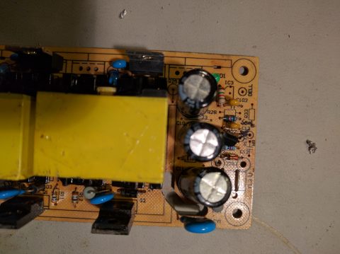
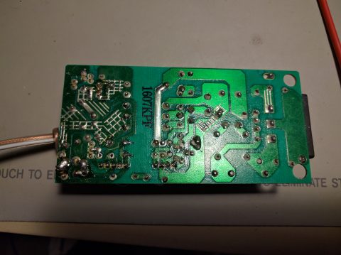
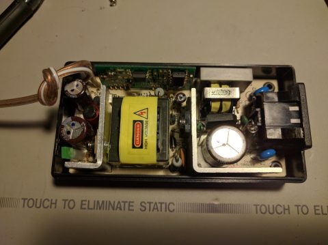 Next, I had a rummage through my box of PSUs looking for something else that might be suitable and came across a PSU rated for 5V @5A, but missing its output cable. I opened it up, clipped my meter to the output terminals, plugged it in, and was greeted with 5V. Thinking back, I think what happened was I stole the output cable to repair another PSU with a damaged cable and tossed the PSU into the box on the principle that 5V @5A would probably come in useful. Again, I started out by reverse engineering the board - very similar to the previous PSUs I've looked at, except this one used an off the shelf module for the controller and feedback circuits using SMD devices. It was impossible to see this board clearly as it was mounted vertically next to the output transformer and capacitors, so I desoldered it and pulled it out.
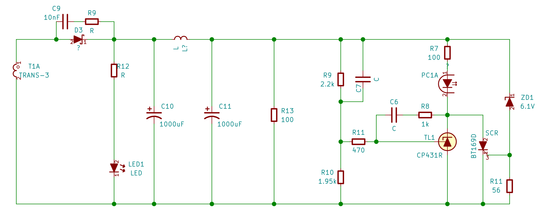
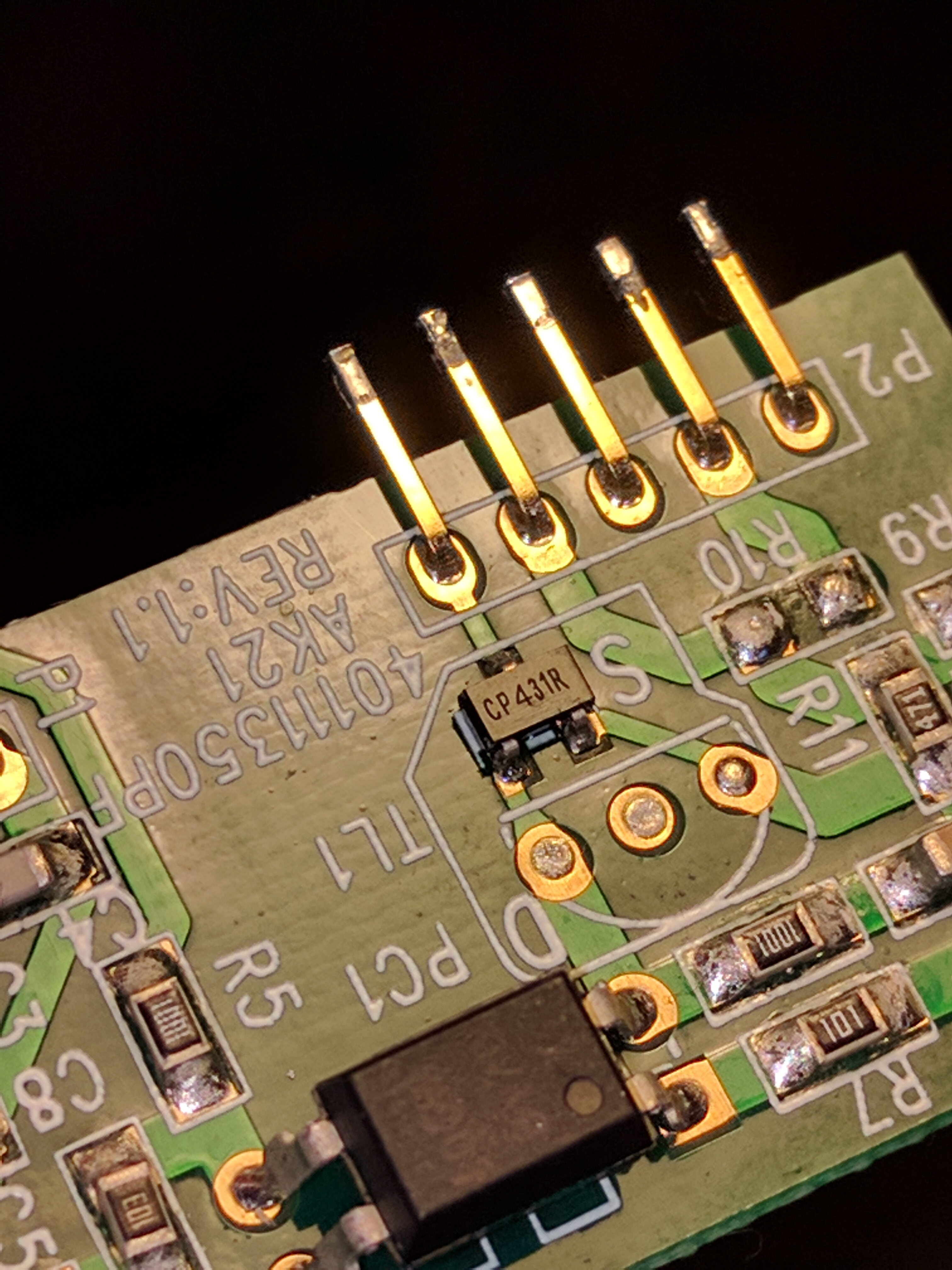
The feedback section consists of a TL231 compatible device, the decoupling capacitors, the optoisolator, and half the potential divider, bringing the centre-point out to a pin where it's connected to ground via a 1.95k resistor. Also on the board was a zener diode feeding the gate of an SCR, which was wired in parallel with the TL231. This provides a hard limit of 6.1V on the output.
Using the formulae above, I calculated that bringing the 1.95k resistor down to 916 ohms would do the trick. This would require a parallel resistance of 1727 ohms, which isn't exactly an E-series value. However, I did have a 1.2k and a 470 ohm resistor, which when wired in series and connected in parallel across the 1.95k resistor give 900 ohms, which should give an output of 8.6V. I removed the zener diode (I'll need to replace it with a 9V zener if this works), added the resistors to the main board, re-attached the control module, and gave it a test. 8.6V on the output, and everything functioning normally! Success - all I needed to do then was attach some wire for the output and put it all back together.
After double-checking the output, I connected it to the V86P, with the hard disk and floppy drive disconnected and powered it on - started up cleanly. I then powered it down, and connected both hard disk and floppy drive. Previously when I'd tried this, it would completely fail to start, with the 5V rail significantly under-voltage. This time, it started up! Both hard disk and floppy working correctly. The system still won't power on when powered from 5 C-cells, so I still think the DC-DC converted on the motherboard needs work, but this is the first time this system has been fully up and running under its own steam since I acquired it.
Leave a comment
You must be logged in to post a comment.