Heating things up a bit
One problem owners of newer houses may be familiar with is the poor insulation of the room over the garage. The cheapest solution is to just put in batted insulation and vapour barrier (basically just plastic sheeting), which ought to be sufficient, but clearly isn't. The end result is the bedroom over the garage is often cold in the winter (and hot in the summer) - it doesn't help that the HVAC run to this room is probably one of the longest, and as builders also don't seem to tape their joints, likely to be subject to a lot of losses along the way. I could probably do a whole post just on things our builder has (or typically hasn't) done to save costs. However, this post documents a little project to help keep the chill out of our daughter's bedroom.
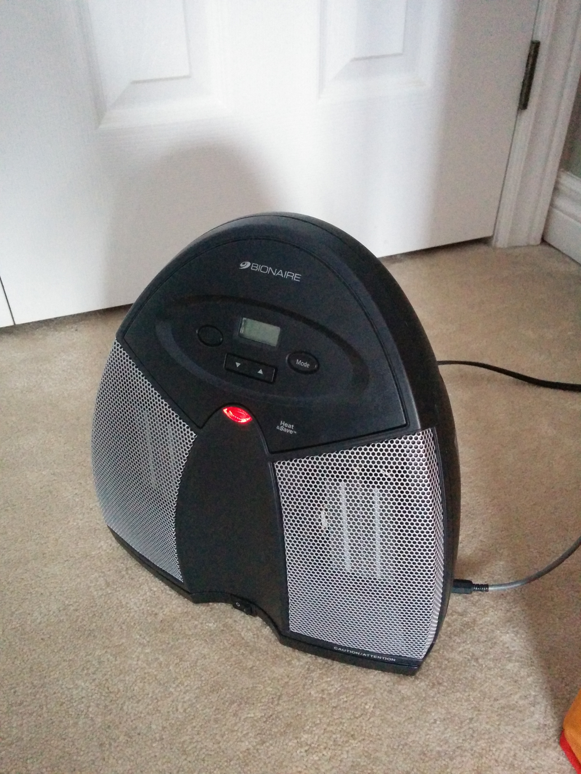
As winter approached and the outside temperature started to drop overnight, it wasn't long before we noticed the temperature in our little front bedroom getting somewhat chilly overnight. Now whilst sleeping in a cool room is meant to be good, this was getting a bit too cool for our liking and out came the little heater we'd purchased the previous year with this particular application in mind. I'd had a look at the available options and read the reviews before settling on a little ceramic fan heater with a digital control. At first glance this seemed quite neat - it had four modes (Low, High, Economy, and Auto), the last of which allowed you to specify the setpoint and it would cycle on and off around that temperature. I'd tested it earlier in the year when I was doing some work in the garage and wanted to take the chill off and it seemed to work nicely. Of course, things are never quite as simple as it seems, and it wasn't long before the shortcomings came to light. First of all, it only let you set down to 18C, which is a little warmer than the 16C sleep folk recommend. Secondly, it seemed to have a couple of degrees hysteresis either side of the setpoint. Thirdly, the temperature sensor was buried inside the housing so it only got a reasonable reading when the fan was running - but there was no way to make it run the fan without the heating elements. All of these combined meant that whilst it did keep the chill off the room, the room temperature would fluctuate between maybe 16C at the lowest and 24C at the warmest extremes. This isn't too bad for you or I, who can pull the covers on and off as required, it doesn't work so well for a baby. A better solution was required.
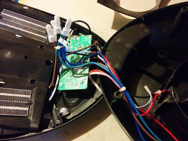
The first step was to open up the heater to see if there was anything wrong, or if it was just poor design. Pulling the cover off revealed a pretty simple design (as expected) with four ceramic heating elements wired in two pairs; a fan; a motor and mechanism in the base to provide optional oscillation; a control/interface board; and a thermistor on the end of a bit of wire. The thermistor was mounted on a little plastic standoff behind the fan, where it should in principle get a reasonable reading so long as there was airflow. The fan was physically wired in parallel with the first (Low) heating element pair, so it only runs when the heat is on. Nothing was obviously amiss (no hot glue over the thermistor, etc), so it was on to the next step: see if it's possible to replace the controller.
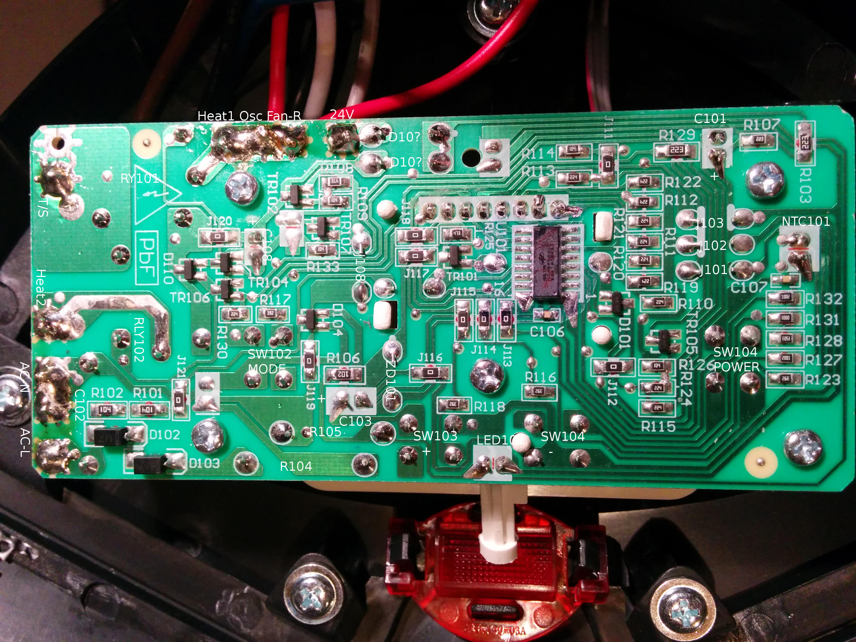
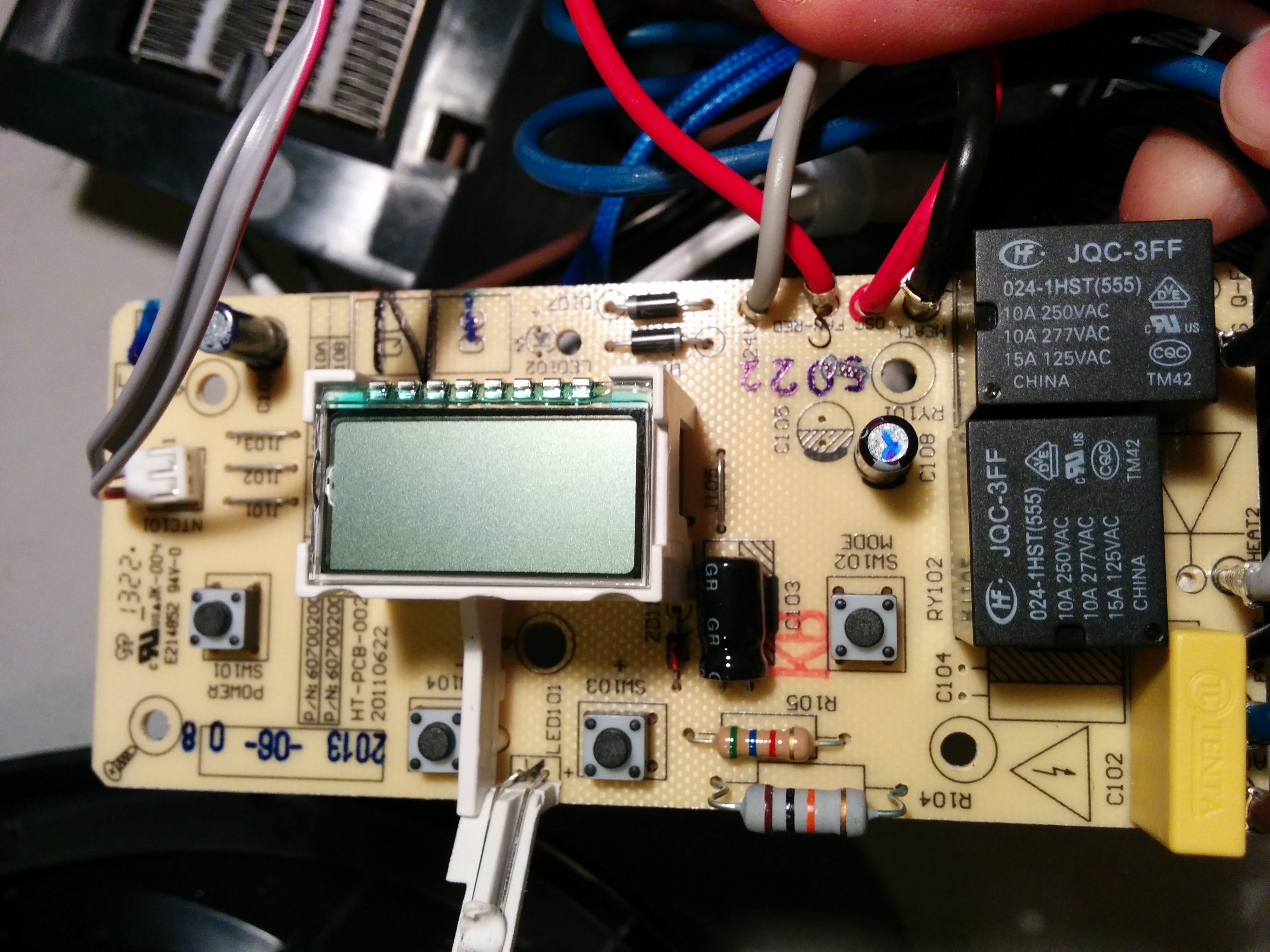
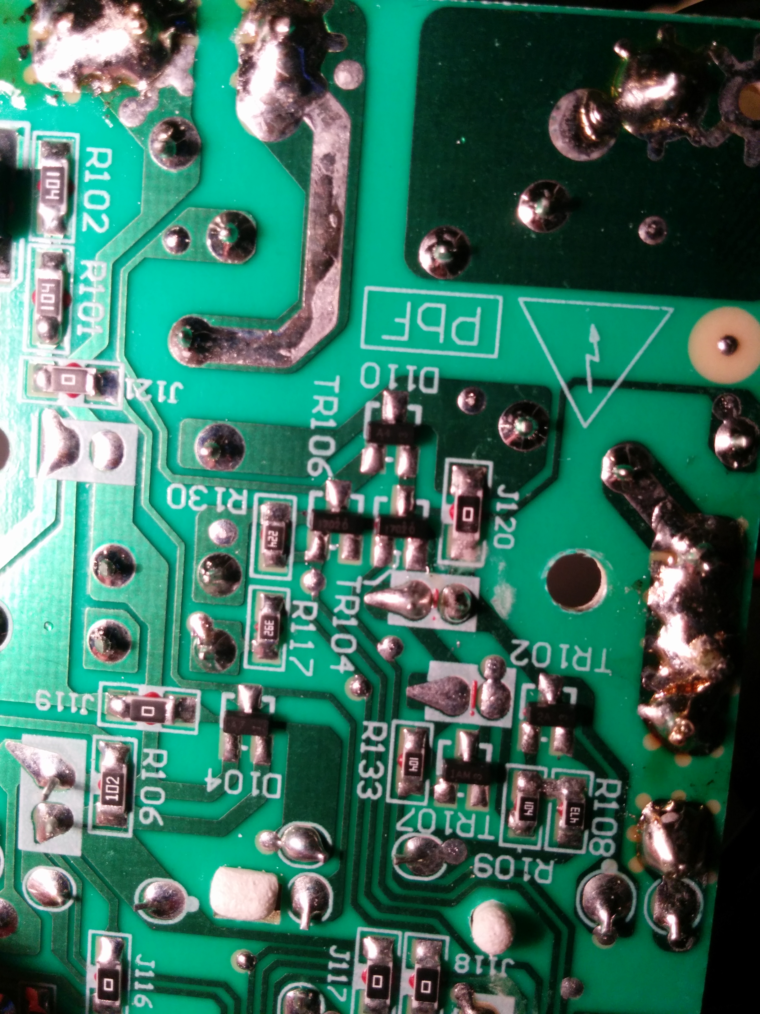
Looking at the control board, it's about what you'd expect: a handful of tact switches; an LCD display; a micro-controller; an LED to show power; a couple of relays; a few diodes; transistors; and a scattering of passives. Starting with the high-voltage side, mains neutral comes in to a wire nut, then out to all the modules (heater, fan, oscillating motor, PCB). Likewise, mains live (120V) goes into a wire nut, then goes to the PCB (AC-L), and through a safety cutout circuit that contains bi-metalic modules acting as thermal cutouts next to each heating module, and a single-use thermal cutout to protect the whole unit against overheating. This then feeds back into the PCB as common for both relays. One relay switches this post-safety Live to the first pair of heating elements (Heat1), the Fan, and the oscillating motor; the second switches it to the second pair of heating elements (Heat2).
At this point, there were two apparent options: 1) build a control board with a pair of relays and put their contacts in parallel with the existing relays; 2) look to see if it's possible to control the existing relays.
Checking with a meter and it appears that there's a 24V DC input to the board to power the micro, provided by fan assembly. Some more probing and the relays coils appear to operate directly off this supply, and it's present even when the unit is in standby mode. Tracing out the board, and it appears that the relay coils go to a common ground, and have a switched +24V input, switched by a pair of n-channel MOSFETS. Bridging +24V to the first coil, and the fan and heat kicks in as expected. Repeating with the second causes the second heating block to kick in. Based on this, it should be simple enough to build a control board that accepts two input signals, buffers them through a pair of optoisolators, powering a pair of MOSFETs wired between +24V and the relay coils (with source and drain in parallel with the existing MOSFETs on the board).

At this point, it's worth giving a thought to safety. The fan is switched by Relay1 (in combination with Heat1), however Heat2 is switched separately. The existing micro has the logic not to turn on Relay2 without Relay1 being on, and whilst the system has three separate thermal cutout devices, I would prefer to avoid relying on them to avert a melty mess (or a fire) in the event of screwing up the input signals. A simple diode OR on the input lines for the Relay1 input should do the trick - now the two inputs become On(low+fan) and On(high+fan), rather than On(heat1+fan) and On(heat2). There's plenty of space in the base of the unit, and there's already a cable bundle passing up into the main unit. It should be possible to mount a board inside and bring the input back to a jack mounted on the bottom edge.

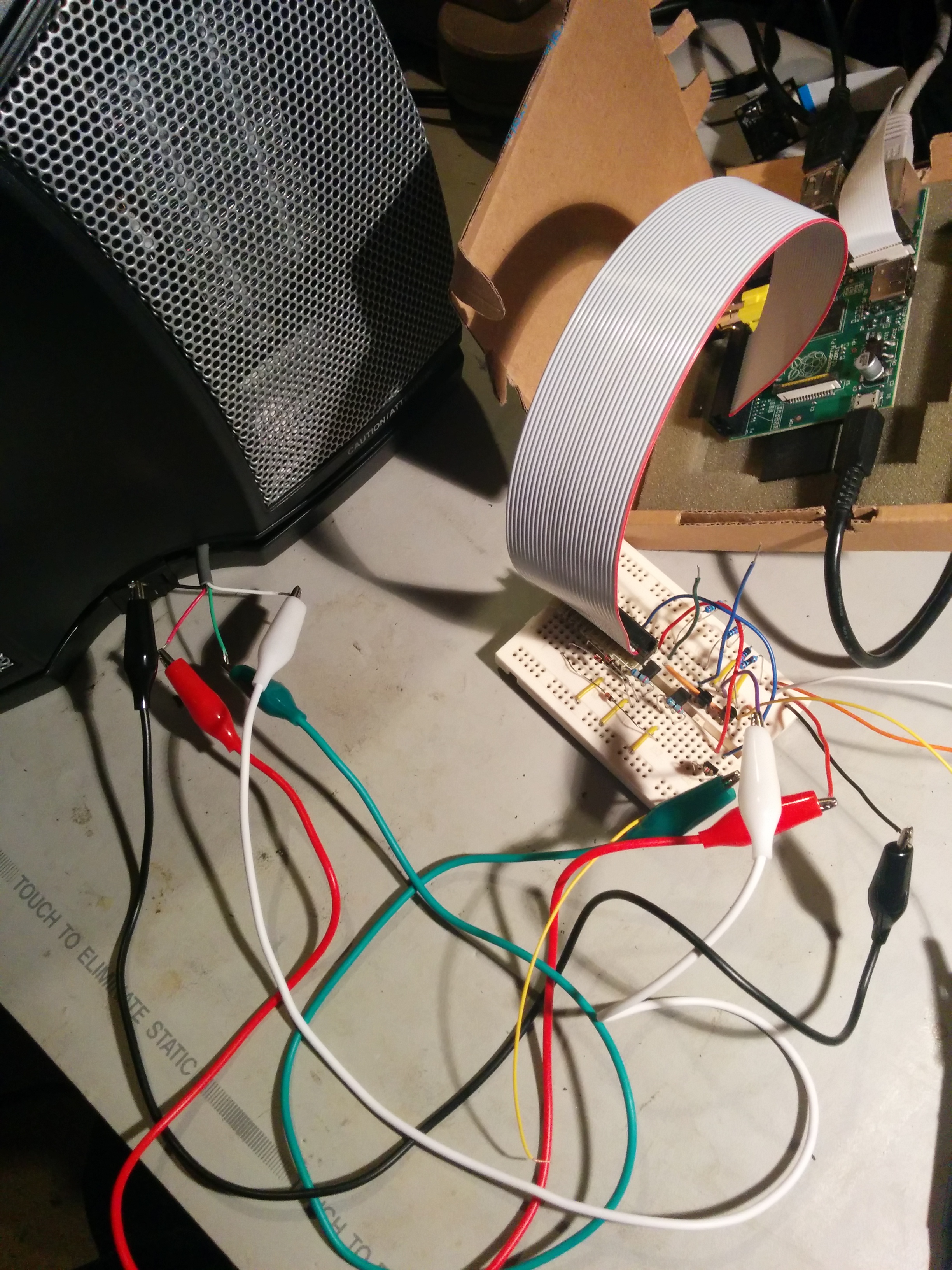
The next step was to sketch up a quick and dirty schematic on paper, and then translate that to a prototype on breadboard. I tacked a four strand cable onto the outputs of the two MOSFETs on the main board, to ground, and to the 24V line, then brought this out to the breadboard. Then I could try applying a 3.3V signal to the input side of the prototype interface, and was pleased to see that it operated as intended - applying a signal to the Low input only caused the fan and first pair of heaters to come on; applying a signal to the high input only cause both heater pairs to come on with the fan.
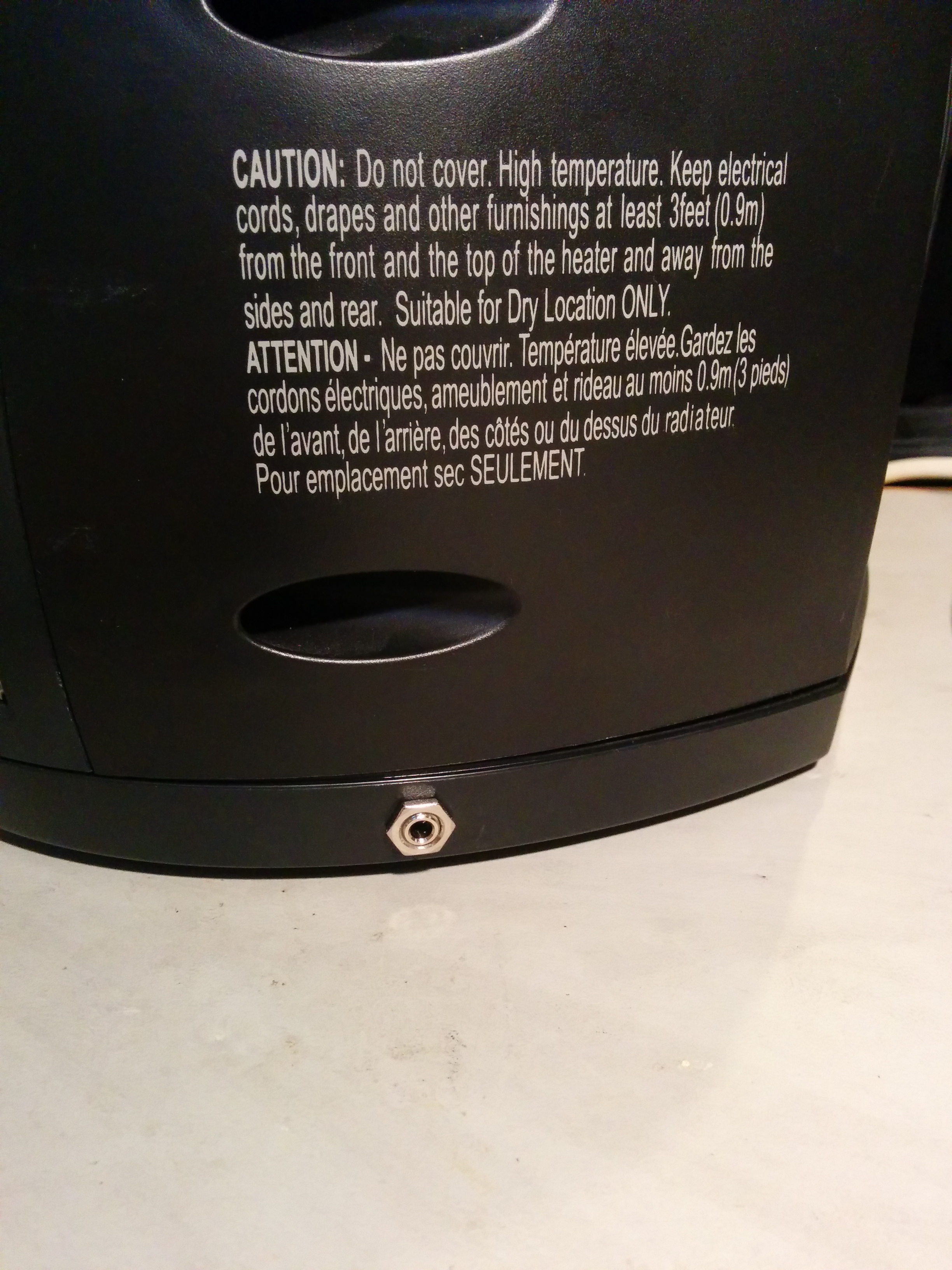
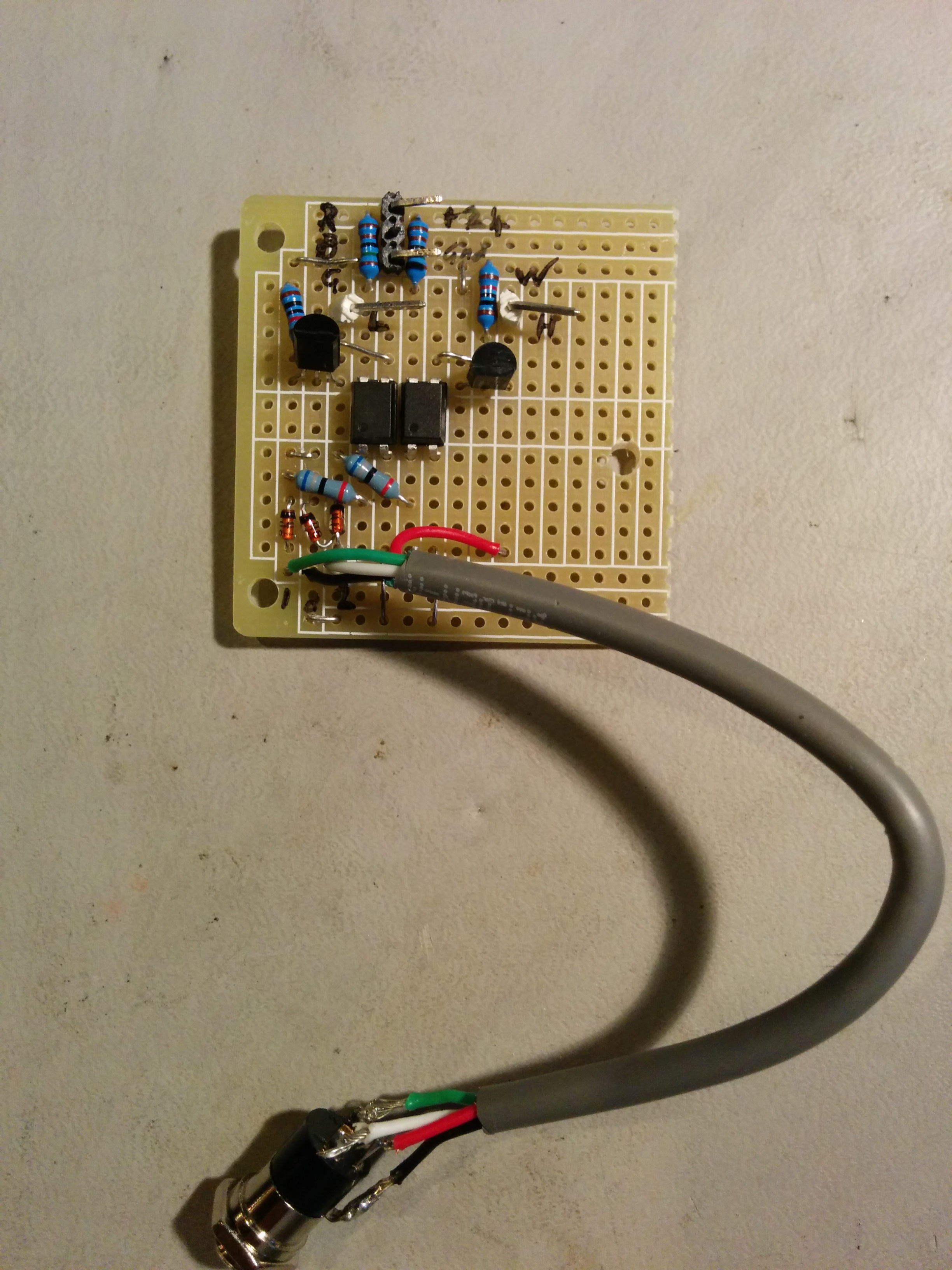
I moved the components over onto a piece of proto-board and mounted that into the base of the heater, along with a 3.5mm TRRS jack as the input. The end result is nice and unobtrusive - the only sign is the little silver-coloured socket mounted on one side of the base, and when nothing is plugged in, it behaves as normal. There's no power exposed on that connector - it just connects to the LED side of the opto-isolators, so if someone plugs in some random thing (like a pair of headphones) it's not going to cause any unpredictable behaviour.
Now the fan is directly controllable by an external system, I needed to build something to control it. The requirements are pretty straightforward - monitor one or more temperature sensors, and toggle the heater on and off to maintain that temperature. Seems an ideal task for a little microcontroller, except I didn't have one floating around. What I did have was a spare Raspberry Pi and a wifi adaptor, so that's what I decided to use for a first attempt. The first thing to do was to write a simple script that could toggle the heater on and off via GPIO pins. Once that was working, the next step was to add in a temperature sensor - I went with the Dallas Semiconductor DS18B20 one-wire temperature sensors. I was originally thinking of mounting one on the housing the Pi, and another external; but in the end, I just went with a single external sensor on the end of a piece of screened cable, with a little heat-shrink boot. I then extended the control script to monitor temperature in a loop, and toggle the heater on and off to maintain a set-point. It's a very simple control loop, with a +/-0.5C hysteresis. I figured I could come back and do something fancier later if required.
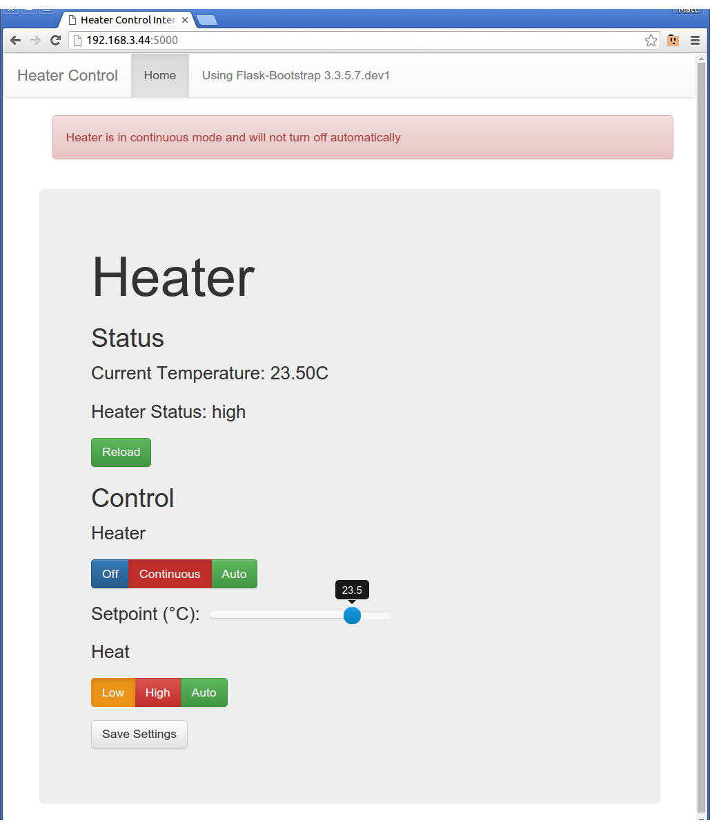
Having a script that could control the temperature was only half the job - there needs to be some sort of user interface. The simple solution is to have an on-off button - which was easy to implement (I actually went with a pair of buttons - on and off), along with an LED to indicate the status. That was the first version - and it worked pretty well - we weren't getting temperature alerts from the baby monitor any more, but there wasn't an easy way to change the temperature (I had to ssh in and change the config file), and there were a few days where we either forgot to turn it on at bedtime and had to sneak back in, or forgot to turn it off in the morning - leaving it to warm the house. It seemed like a logical next step to throw a simple web interface on there which could be accessed from any browser on the local network. I also added a cron job to turn the heater off in the morning so we didn't accidentally leave it on all day.
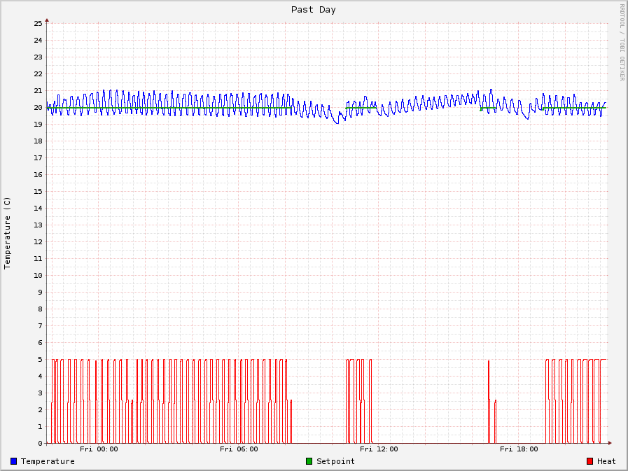
It wasn't long before I was curious as to what the temperature looked like, so I threw rrdtool on there and set it to log temperature, setpoint, and heater status. Once I started tracking that, it was clear the simple control loop was working incredibly well - the heater wasn't cycling excessively and the temperature wasn't deviating by more than half a degree.
We ran like this all winter and it was great. Then we discovered the builder had made a mess of our loft insulation, so we fixed that. Guess what? After that, we don't need the heater any more, and the insulation over the garage seems to be adequate after all. Oh well - it was a fun project 🙂
Edit: I forgot to mention - the code's up at https://github.com/mattinx/heater in case anyone's interested
Leave a comment
You must be logged in to post a comment.