Floppy Disk Drive ID Switcher
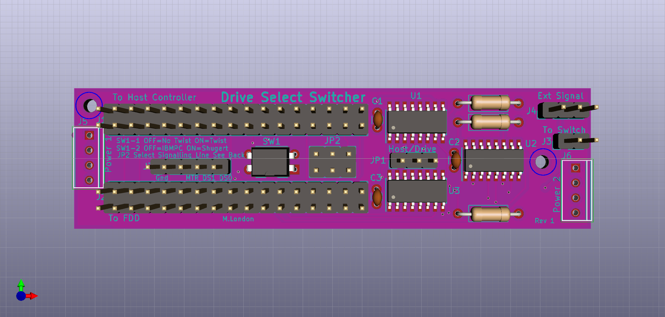
Currently a work in progress - I'll update this with more information as I go.
This little project came about when I started using a Gotek floppy emulator with some of my retrocomputers. Having hundreds of floppy images available at the push of a button is great, not to mention the lack of read/write errors and degrading media; however it's somehow not the same experience as physically swapping disks, and even with some of the sound hacks, it just doesn't sound right. For this reason, I like to keep floppies around in addition to using a Gotek, and it's easy enough to have both connected to a machine at once. Where things get marginally more complicated is when you want to change whether to boot from the FDD or the Gotek. Many systems only boot from the first drive (0 or A), and even in cases where you can tell it to boot from a different drive, a lot of games assume their disk is in the first drive.
Heating things up a bit
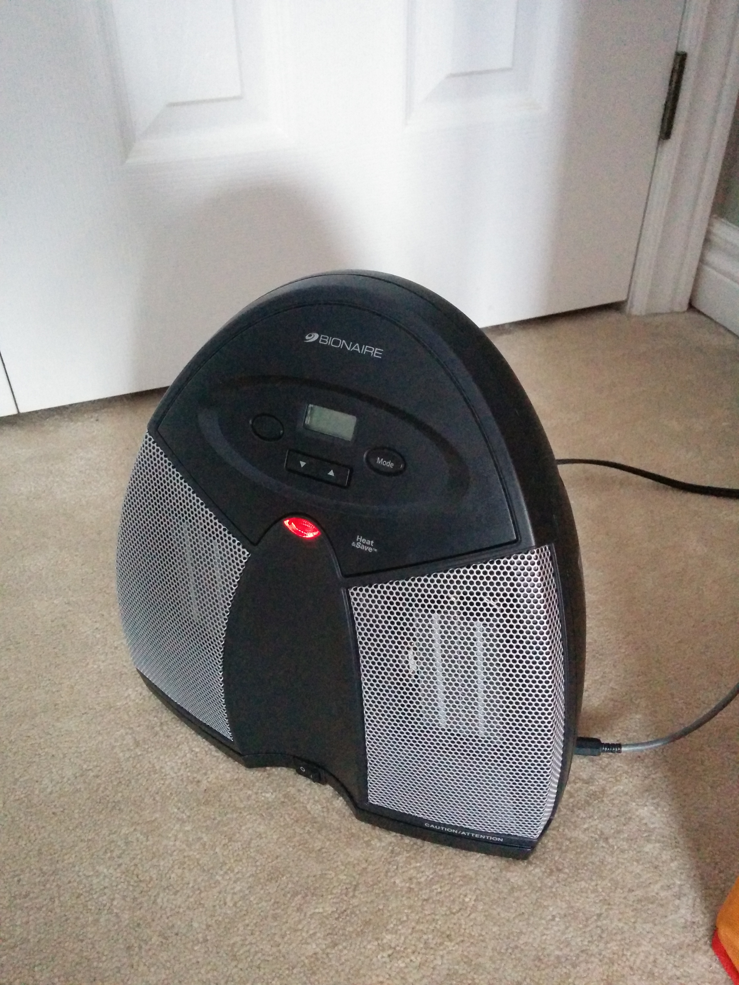
One problem owners of newer houses may be familiar with is the poor insulation of the room over the garage. The cheapest solution is to just put in batted insulation and vapour barrier (basically just plastic sheeting), which ought to be sufficient, but clearly isn't. The end result is the bedroom over the garage is often cold in the winter (and hot in the summer) - it doesn't help that the HVAC run to this room is probably one of the longest, and as builders also don't seem to tape their joints, likely to be subject to a lot of losses along the way. I could probably do a whole post just on things our builder has (or typically hasn't) done to save costs. However, this post documents a little project to help keep the chill out of our daughter's bedroom.
Retrochallenge Roundup (and a quick JVC update)
Well, it's the final night of RetroChallenge, so it's time for a closing post. As I'd expected, I didn't get anywhere close completing my goals, with lack of time being the age-old excuse. However, it was still a very productive project and I plan to keep pressing on and making semi-regular posts. Hopefully I can keep the momentum going even through RC is over for another 6 months. Although I didn't get a wiki up and running to store the information I was gathering, it's all up on this blog - so that's a start as far as making it available is concerned.
Other key milestones:
- I hacked together a working PSU for the V86P - learning a lot about switch-mode PSUs in the process
- I reverse engineered the output stage of the original PSU, using photos and some measurements being taken remotely, and captured the result as a kicad schematic
- I'm most of the way through a PCB layout for the charging section of the PSU, which will provide all the necessary voltages to the V86P to run and charge the NiCd pack given only a sufficiently beefy 8.5V PSU. The missing piece is finding a case I like, then I need to tweak the board dimensions to fit
- II got the V86P running with both its internal HDD and FDD
- I found datasheets for most of the key ICs in the system
- I'm about half-way through mapping out the pinout of the hard disk controller to motherboard interface pinout
- I confirmed the pinout of the 26-pin JVC interface
- I identified the SHIP_READY and SERVO_GATE lines as signal that the heads were parked and a sector index respectively
- I identified that DOS sees a 4 head disk with 512 byte sectors, but the disk itself only has one head select line - possibly there's some logic for splitting 1k sectors into two logical heads - developing some basic C routines to call BIOS int13h
- I've confirmed I can read the ECC blocks from the data block via DOS int 13h calls, which should make reverse engineering the polynomial used by the controller relatively straightforward
- And lastly, which I'm going to cover below - I think I've finally confirmed the disk is storing 2,7 RLL encoded data
The JVC 26-pin Interface – Part 2
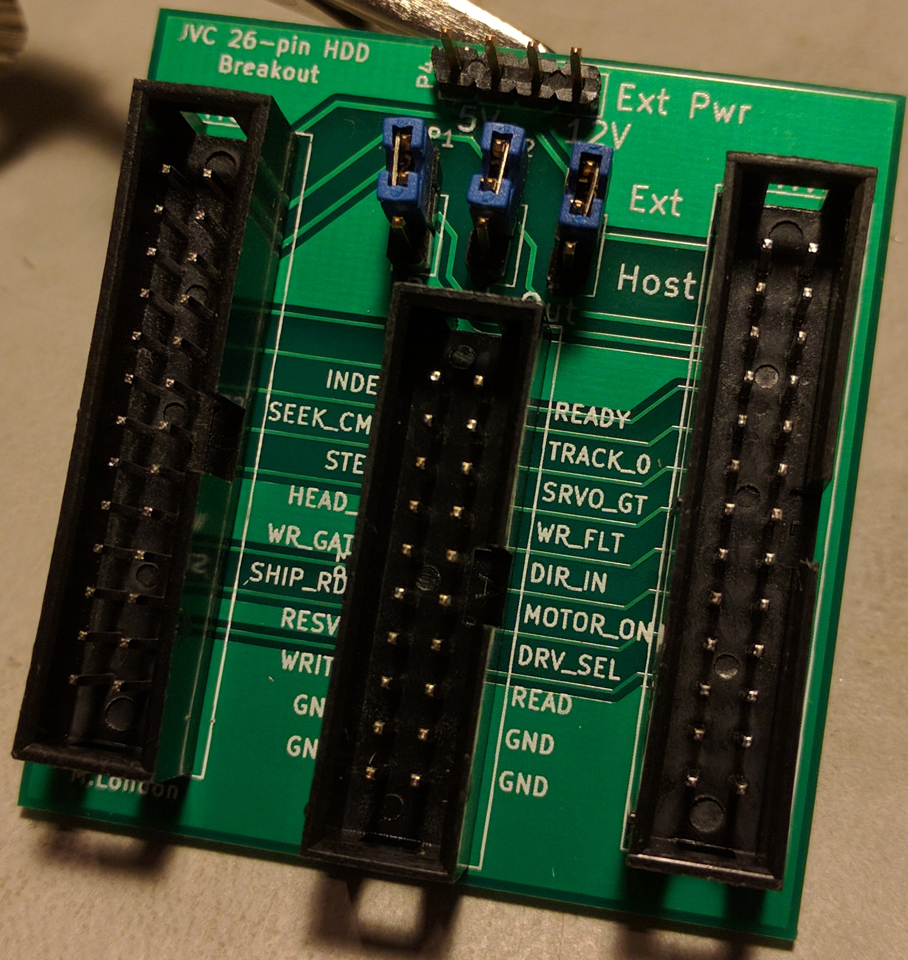
Welcome to the second part of my adventures with this slightly unusual hard disk interface. The more I dig, the more questions I raise - it's certainly good for raising the overall feeling of confusion. I think overall I'm making progress, but I'm still a long way away from even considering disk emulation (which was the original aim). As a quick recap of my previous posts - I designed a breakout board which brings the 16 lines of the 26-pin interface that aren't power or ground out to a pin header, along with support for supplying external power to the drive. I also got a power supply working so the laptop can run under its own steam, with both hard disk and floppy drive working correctly. I've got datasheets for most of the chips on the controller, and they look to be a standard ST506/412 RLL chipset, although with a few subtle differences and a mystery JVC chip - I've been reading through those and generally learning more about MFM than is probably necessary in 2017, but hey, isn't that what this hobby is all about?
Retrochallenge Half-Time Round-up
Well, I meant to write this up at the weekend, but that didn't happen. Better late than never - it's time for a half-time round-up, or perhaps a review of quite how much has been added on to my to-do list for this project. It really does seem to be one of those things where it appears complicated at first, then you get into it, and discover there's a significant number of smaller tasks you hadn't thought of to begin with. Despite the mamoth amount of work outstanding, it's actually been a pretty productive first half of the challenge, and I'm certainly enjoying it.
In which the author comes to grips with the SMPS
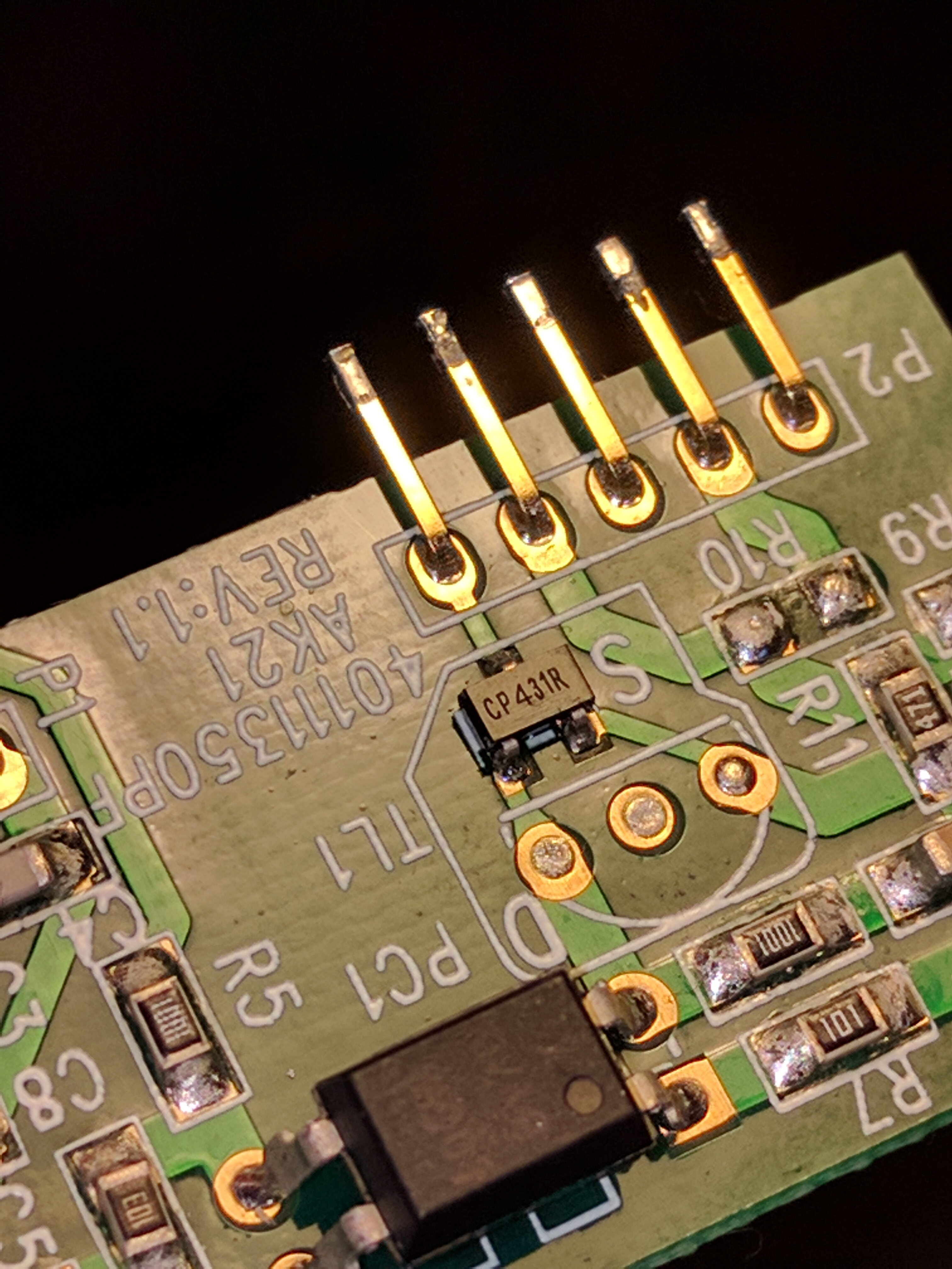
Power supplies are probably something we all take for granted. Pretty much everyone knows that if you plug an electronic device into the power outlet on the wall, there's a thing called a power supply that somehow converts the mains voltage to something lower (and safer). I suspect most people reading this post know at least a little more than that, maybe something about transformers. Perhaps like me, you're familiar with unregulated DC supplies (step down the AC voltage with a transformer, rectify it with some diodes, then smooth it with some big capacitors) and linear regulators (take an unregulated DC voltage and essentially dump the excess above the preset output voltage as heat), with a vague awareness that Switch Mode Power Supplies are far more common these days, and much more efficient.
It’s all been a bit quiet
So apparently I set this up, and completely failed to keep up with posts. I've got a bunch of things I intended to write up, so if you're one of the few people who comes across this site, there'll be some more content soon - I hope
Adding composite video out to the +3
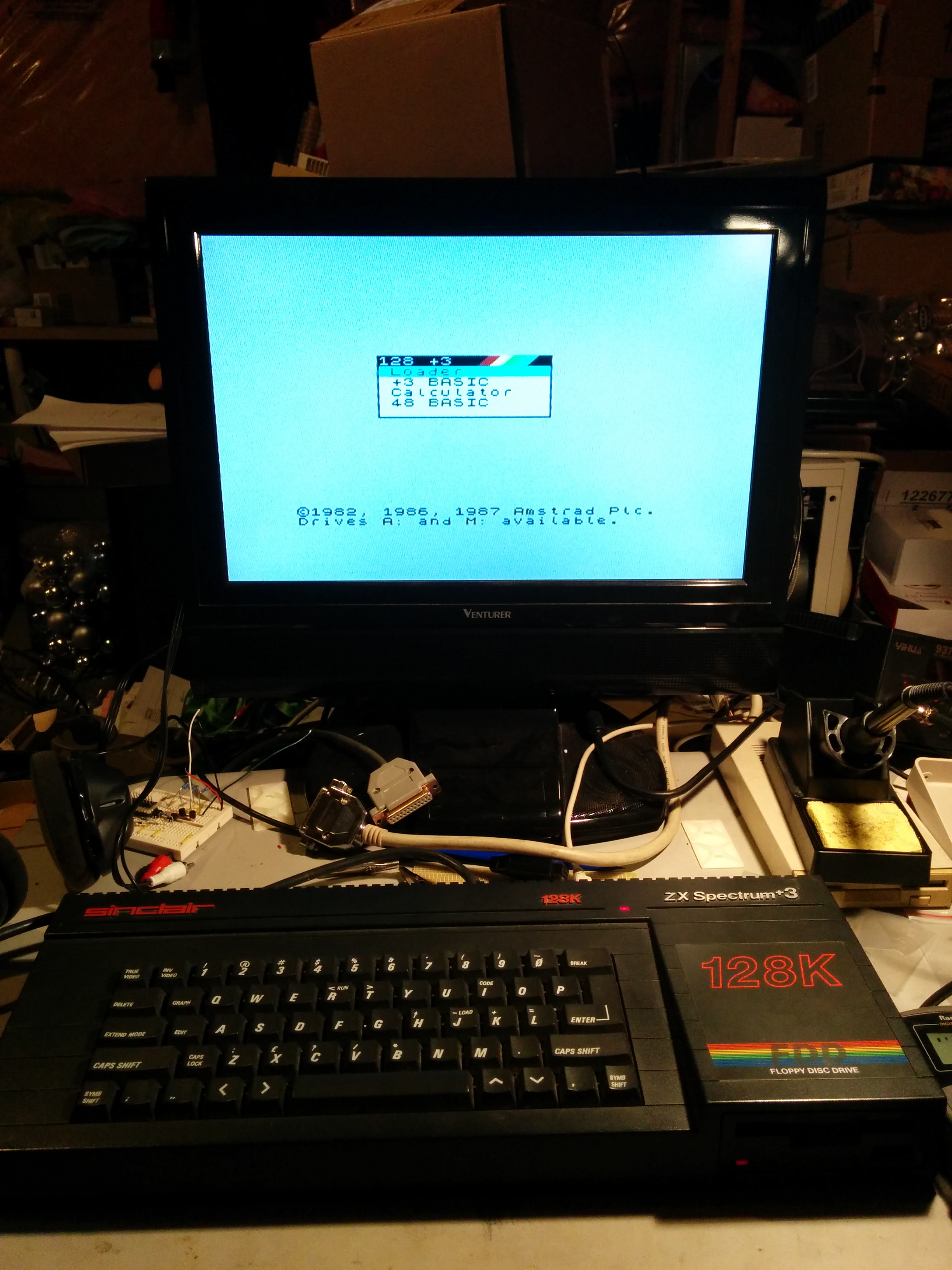
Now I have a working power supply for the Spectrum +3, I need some way to see what's being output. In its original configuration, video is output either a PAL RF signal on UHF channel 36 (UHF 36 was used a lot like VHF 3/4 in north america) or as RGB on the Peritel socket. The RGB signal doesn't help much here - whilst in the UK, TVs have a SCART socket with RGB inputs, in north america, TVs have YCbCr component inputs, so some circuitry to do conversion is required. That being said, the RF signal is generated from a composite signal - in earlier model Spectrums, it's just a matter of disconnecting the input to the modulator, disconnecting the output of the modulator from the socket, and connecting the input to the socket. Unfortunately, with the later model Spectrums, Amstrad mixed in the audio (as an FM signal), and that tends to upset TVs when you include it on the composite video input.
Retrochallenge 2016/01
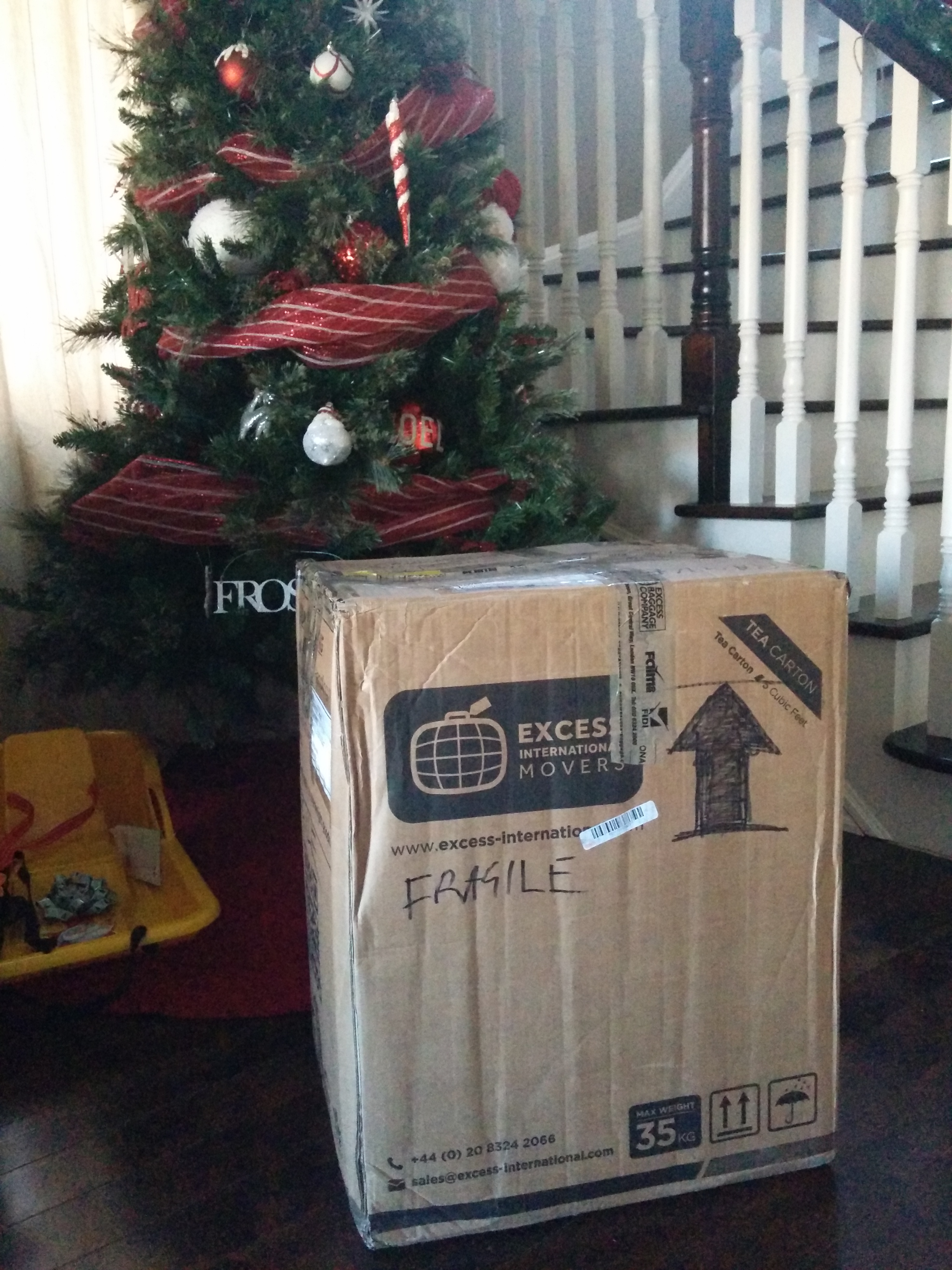
As I'd mentioned in a previous post, when we were over visiting my Mum last year, I filled a 4.5cuft box with fun bits and pieces from my childhood, including my Amiga 1200, Spectrum +3, and two 48k ZX Spectrums that aren't very happy. Well, the box arrived on Christmas Eve, just in time to go (almost) under the tree.
My love-hate relationship with pre-lit trees
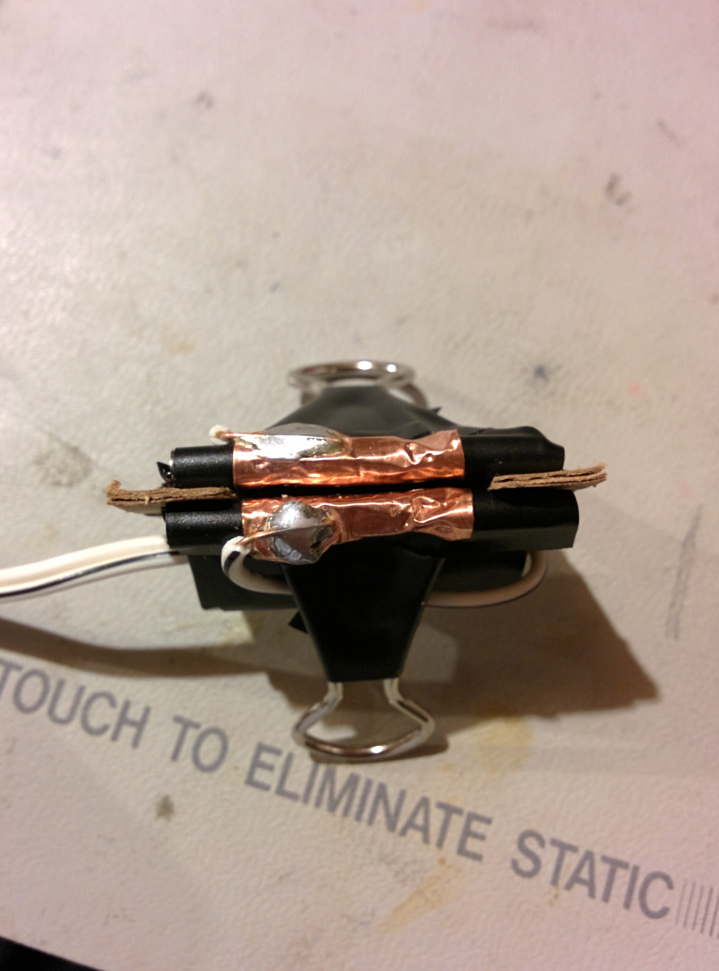
It's that time of year where we start to pull out the Christmas decorations. Now before you start, yes - I know it's only November, but when you have six trees to put up and decorate along with all the other decorations, you need to start early. If you've looked at Christmas trees in the shops recently, you'll see that there's a big trend toward pre-lit trees. If you haven't, the idea is that instead of having a long string of lights in a box that you have to slowly unwind onto the tree, the tree has several strings of lights already attached to the branches so all you have to do is fluff the branches and plug it in.
Incandescent Christmas lights are pretty neat little things. They're not just a simple filament bulb - they also have a shunt which is intended to short out the bulb in the event that the filament breaks. This means that when you have a long strand of bulbs wired in series and one fails, it doesn't cause the whole strand to go out. It usually works, but not all the time. As bulbs fail short, the overall resistance of the strand drops, and in accordance with Ohms law, the current in the strand increases. This in turn means that the likelihood of another bulb failing increases, and so on until either a bulb fails open or the whole strand is toast.